
Method for calibrating inertial sensor installed in arbitrary position on board vehicle and sensor system of dynamics of vehicle able to be installed on board in arbitrary position

a technology of inertial sensor and vehicle, which is applied in the direction of instruments, navigation instruments, structural/machine measurement, etc., can solve the problems of concentrating an excessive error, difficult to set positioning in all vehicle models, and requiring an excessive installation time, etc., to facilitate the installation of inertial sensors, low errors, and simple implementation

Active Publication Date: 2012-12-27
FAB ITAL MAGNETI MARELLI SPA
View PDF6 Cites 31 Cited by
  • Summary
  • Abstract
  • Description
  • Claims
  • Application Information

AI Technical Summary

Benefits of technology

[0019]An advantage of the of the calibration method according to the invention is that it facilitates the installation of an inertial sensor—such as an attitude or movement sensor (in an embodiment, a tri-axial sensor)—on board a vehicle according to an arbitrary orientation, but making it possible to detect attitude or movement data of the vehicle that can be related to the main axes of the vehicle itself to be used for significant applications only in the context of a reference system centred on the vehicle.
[0020]Another advantage of the of the calibration method according to the invention is that it provides a satisfactory solution to the problem outlined above, avoiding the drawbacks of the related art.
[0021]Another advantage of the of the calibration method according to the invention is that it calibrates an inertial attitude- or movement-sensor device installed on board a vehicle in an arbitrary position and is as accurate as possible, with low errors in determining the coefficients of the coordinate-transformation matrix between the local reference system of the sensor device and reference system of the vehicle.
[0022]Another advantage of the of the calibration method according to the invention is that it is automatic; requires simple implementation, minimal computing burdens, and low power consumption; and favors speed and accuracy of execution.

Problems solved by technology

Both in the first and, above all, second case, however, it is not easy in all vehicle models to set positioning constraints of the sensor device so that its local measuring axes are aligned with the main axes of the vehicle.
Constraining the installation of such a sensor device to its correct orientation with respect to the main axes of the vehicle would require an excessive installation time (for accurate installation and for checking that the constraints and the correspondence of the measurements are respected).
Disadvantageously, this mixed approach, which reduces the physical measurements to the minimum and fills in the data of the coordinate-transformation matrix based on pure mathematical orthogonality relationships existing between the axes of the reference systems, results in the propagation of measurement errors suffered by the six measurements also on the three items of data collected and causes the risk of concentrating an excessive error on one of the measurement axes, which would significantly compromise the functionality of the application that is based on the accelerometer data of the vehicle.

Method used

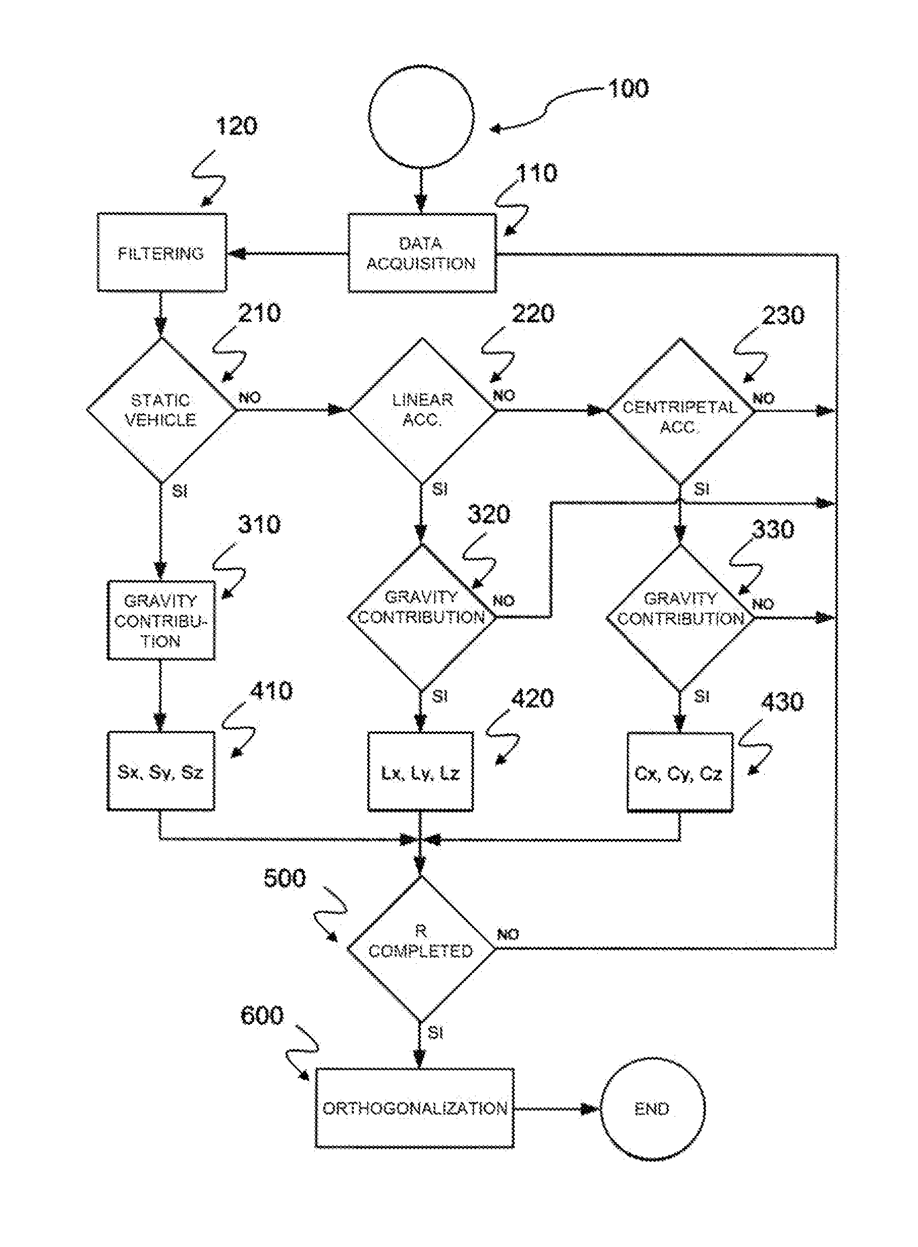
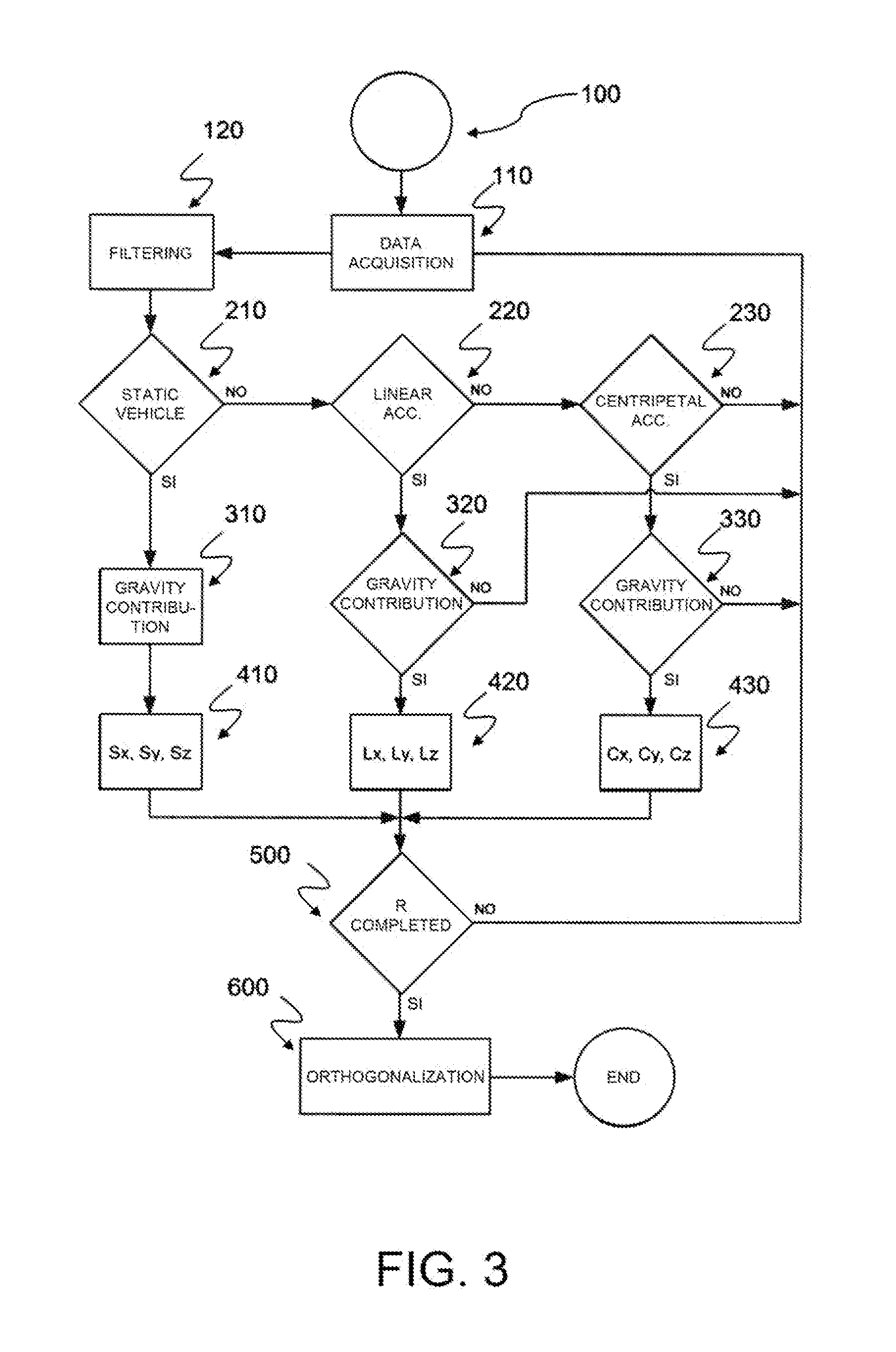

Image

  • Method for calibrating inertial sensor installed in arbitrary position on board vehicle and sensor system of dynamics of vehicle able to be installed on board in arbitrary position
  • Method for calibrating inertial sensor installed in arbitrary position on board vehicle and sensor system of dynamics of vehicle able to be installed on board in arbitrary position
  • Method for calibrating inertial sensor installed in arbitrary position on board vehicle and sensor system of dynamics of vehicle able to be installed on board in arbitrary position

Examples


Embodiment Construction

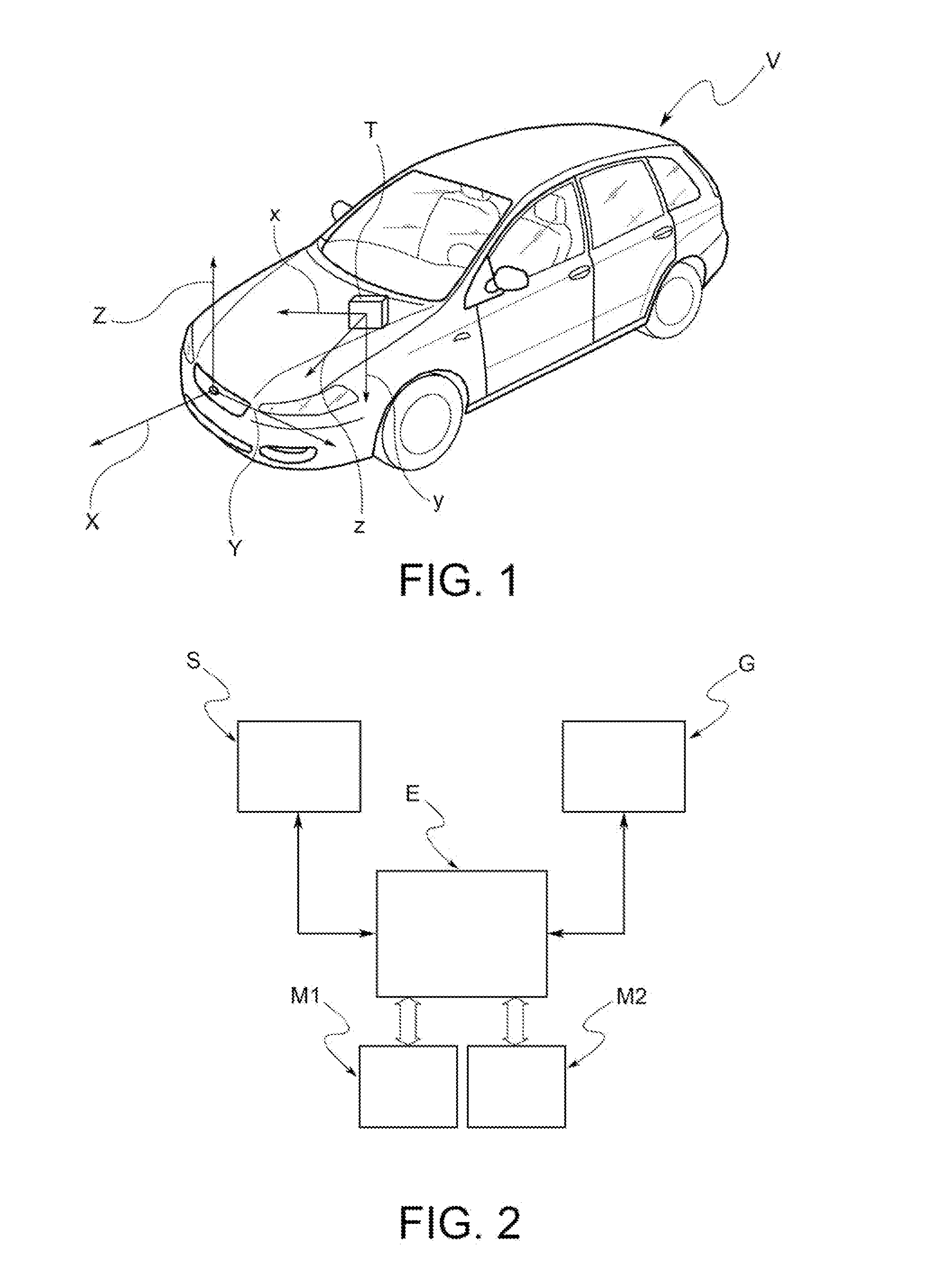
[0029]In the figures, like letters and numerals are used to represent like method steps and structure. In FIG. 1 the letter “V” generally indicates a vehicle, equipped with a telematic unit “T” arranged to detect the dynamic conditions of the vehicle—in particular, adapted to measure the accelerations undergone by the vehicle while travelling as a function of the different driving conditions.

[0030]The telematic unit “T” includes an attitude- or movement-sensor device “S”—for example (but not exclusively), a three-axis accelerometer device—installed in an arbitrary position and adapted to measure the linear and centripetal accelerations undergone by the sensor in the components directed according to the local axes of the device, identified in the figures as “x,”“y,” and “z.”

[0031]Again in FIG. 1, “X,”“Y,” and “Z” indicate the main axes of the vehicle, commonly identified as longitudinal, transversal, and vertical axis and with respect to which the movements of the vehicle are defined...


PUM


Abstract

A method calibrates an inertial-sensor device installed in an arbitrary position on board a vehicle and adapted to detect at least one entity indicative of vehicle dynamics along at least one direction of a local reference-coordinate system. The method includes steps of: acquiring by the inertial-sensor device at predetermined measuring times real-measured data indicative of the vehicle dynamics in the local reference-coordinate system; acquiring by a calibrating detector different from the inertial-sensor device, at sampling times coinciding with the measuring times, reference-measured data indicative of the vehicle dynamics in a vehicle-coordinate system; and generating a coordinate-transformation matrix adapted to correlate the entity measured in the local reference-coordinate system with a corresponding entity in the vehicle-coordinate system. Also, a sensor system of dynamics of the vehicle is able to be installed on board in an arbitrary position.

Description

CROSS-REFERENCE TO RELATED APPLICATION[0001]This application claims priority to and benefit of the filing date of Italian Patent Application TO2010A001062 filed on Dec. 24, 2010 and entitled “Method for Calibrating an Inertial Sensor Installed in an Arbitrary Position on Board a Vehicle, and Sensor System of the Dynamics of a Vehicle Able to be Installed on Board in an Arbitrary Position.”BACKGROUND OF INVENTION[0002]1. Field of Invention[0003]The invention relates, generally, to installation and operation of inertial sensors—for example, attitude sensors (gyroscopes) or movement sensors (accelerometers)—on board a vehicle and, more specifically, to a calibration method of an inertial attitude or movement sensor installed in an arbitrary position on board the vehicle and a sensor system of dynamics of a vehicle.[0004]2. Description of Related Art[0005]There is increasingly common use of vehicles that have inertial sensors, such as attitude or acceleration sensors, installed on board...

Claims


Application Information

Patent Timeline
Patent Type & Authority Applications(United States)
IPC IPC(8): G06F19/00
CPCG01C25/005G01C21/165
Inventor DE TOMMASI, CLAUDIO
Owner FAB ITAL MAGNETI MARELLI SPA
Learn More