Rising cable with stabilized driver

Inactive Publication Date: 2013-01-03
GEMO D G MORITZ
View PDF7 Cites 4 Cited by
  • Summary
  • Abstract
  • Description
  • Claims
  • Application Information

AI Technical Summary

Benefits of technology

[0012]According to the invention, the driver is designed as a metal-cast body. A metal casting is a reliable casting technique and shows fundamentally higher strength than for a plastic spray-cast body or a crimped-on sheet-metal part, for instance. A further advantage is the fact that the metal casting occurs at higher temperatures, at which plastic materials have already melted. In casting, any possible interfering plastic part on the rising cable, such as, for example, flocked-yarn thread between coil windings, do not need to be removed prior to the casting. The weakened area next to the recess is provided with an embedded axiparallel bolt, which serves as reinforcement and can be constructed in a manner suitable for this, for example, of steel. For better connection and transfer of forces with the cast material, the bolt can be provided, for example, with grooved surfaces.
[0013]An additional problem is the drive of a sliding element of two sides here with rising cables that have a certain drive-play in the gear-wheel mesh. Consequently, one side of the sliding element is already moving somewhat farther than the other. These insignificant differences in the millimeter range can, however, quite trouble the eye of the observer, particularly in high-priced limousines. Hence, it is advantageous to fasten to the driver a spring projecting over it, which is eminently suitable for eliminating the oblique-position problem. The sliding-roof drive can be constructed

Problems solved by technology

An additional problem is the drive of a sliding element of two sides here with rising cables that have a certain drive-play in the gear-wheel mesh.

Method used


Image

  • Rising cable with stabilized driver
  • Rising cable with stabilized driver

Examples


Embodiment Construction

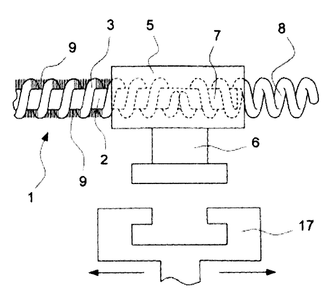
[0019]FIG. 1 shows a rising cable 1 with a flexible core 2, which is formed, for example, from wires counterwound in many layers. On the core 2 is a coil 3 made of suitable thicker wire tightly wound up. The rising cable thus designed can be used as a rack; however it has in addition a round cross-section and is bendable.

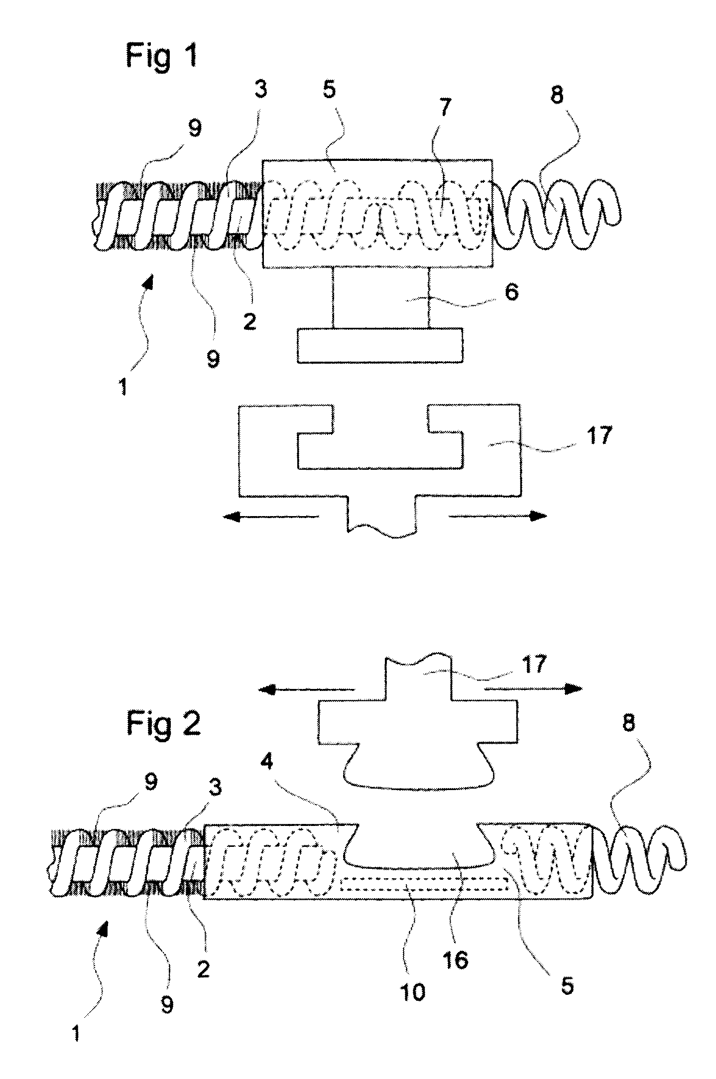
[0020]In the end area of the rising cable 1 depicted by dashes, this is embedded in a driver 5, which is designed as a zinc pressure-cast body. Laterally projecting from the driver 5, a coupling linkage 6 is constructed, which is intended for lateral form-fit operation on a sliding element 17 of a sliding roof, not depicted.

[0021]In the end area depicted of the rising cable 1, the coil 3 is removed. At the free end-area 7 of the core 2, a spring 8 is put on, which is cast in the main body 4 of the driver 5.

[0022]As FIG. 1 shows, the rising cable 1 outside the drivers 5 between the windings of the coil 3 is flocked with tiny hairs 9. These can, for example, be dispos...


PUM


Abstract

In a rising cable (1) with a driver (5) which is fastened at its one end and is configured for coupling to a sliding element (17) which can be moved in the axial direction of the rising cable (1), the driver (5) is configured as a cast metal body which is cast around the end region of the rising cable (1), and said driver (5) has a lateral recess (16) which is configured for coupling and is arranged in the axial direction on the other side of the end of the rising cable (1), wherein an axially parallel pin (10) is cast integrally in that cross section of the driver (5) which remains next to the recess (16).

Description

BACKGROUND OF INVENTION[0001]1. Field of Invention[0002]The invention concerns a rising cable with a driver.[0003]2. Description of Related Art[0004]A rising cable exhibits a flexible core, which is usually constructed in many layers out of counterwound wires. Around the core is a coil made of wire wound in rigid compression and actually with a considerable thread distance between the windings. A driver serves for coupling to a driven element.[0005]Important areas of application are drives for the sliding roofs of vehicles and similar uses such as, for example, a drive for light-protection shades in vehicles.[0006]In these applications, a sliding element, thus, for example, a movable sliding roof, is coupled on both sides to one driver each of a rising cable. The rising cable runs around the section of the sliding roof to a common drive, where it is with the gear wheel in gear, which meshes in the winding pitch of the rising cable, and this operates like a rack.[0007]As a result, th...

Claims


Application Information

Patent Timeline
IPC IPC(8): F16H19/04
CPCF16C1/14Y10T74/18096F16C1/20
Inventor STENZEL, KLAUS
Owner GEMO D G MORITZ
Why Eureka
Try Eureka