Terminal box for use with solar cell module

a solar cell module and terminal box technology, applied in the direction of cooling/ventilation/heating modifications, basic electric elements, casings/cabinets/drawer details, etc., can solve the problem of troublesome diode rectifying function, heat easily tends to stay in silicon resin, etc., and achieve the effect of reducing the amount of sealing material to be introduced

Inactive Publication Date: 2013-01-03
SUMITOMO WIRING SYST LTD
View PDF6 Cites 5 Cited by
  • Summary
  • Abstract
  • Description
  • Claims
  • Application Information

AI Technical Summary

Benefits of technology

[0016]A seal material comprising an insulating resin is introduced into the surrounding portion to be cured after connection of the lead to the lead connecting portion. Since the seal material is not introduced into the diode side even though introduced into the surrounding portion, an amount of the seal material to be introduced can be reduced.
[0

Problems solved by technology

However, since each diode is doubly resin-sealed by the silicon resin and the cover, there is a problem that the heat easily tends to stay within the silicon resin.

Method used


Image

  • Terminal box for use with solar cell module
  • Terminal box for use with solar cell module
  • Terminal box for use with solar cell module

Examples


Embodiment Construction

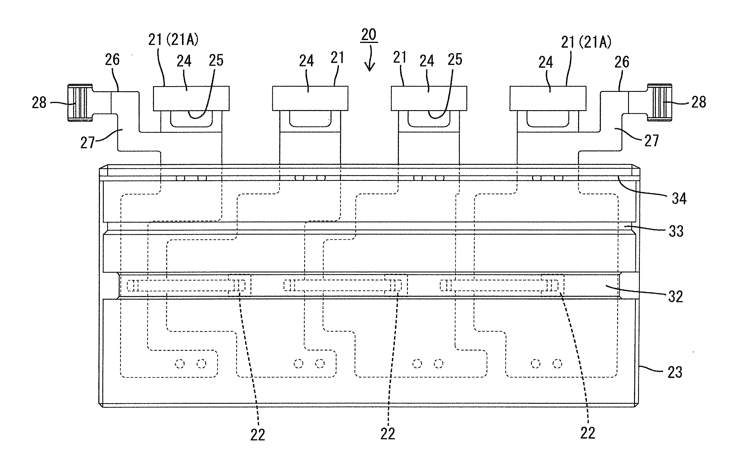
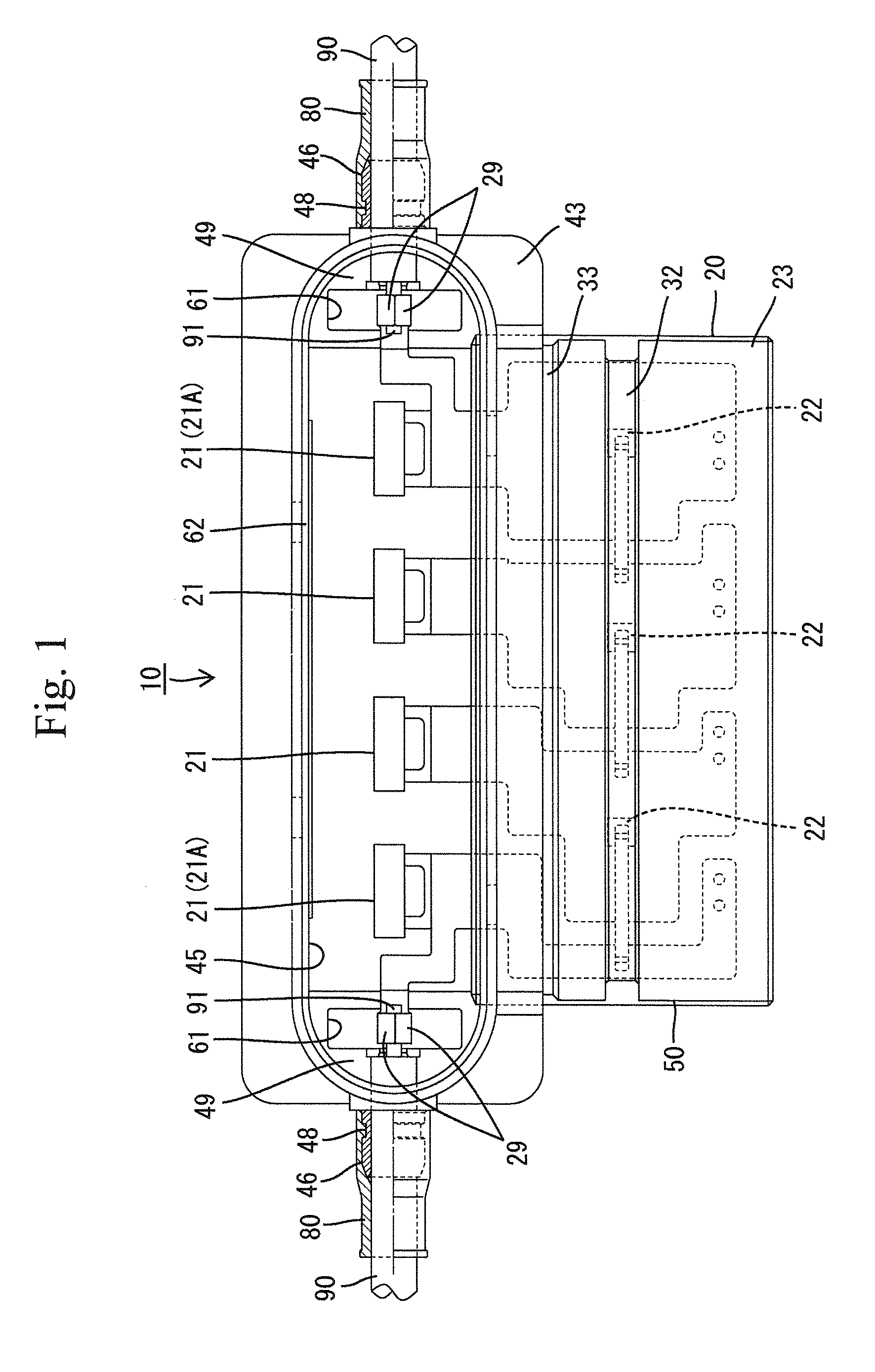
[0025]An embodiment of the present invention will be described with reference to FIGS. 1 to 7. A terminal box for use with a solar cell module (hereinafter, “terminal box 10”) is to be mounted on the underside of a solar panel 100 (see FIG. 7) provided with a multitude of serially interconnected solar cells. The terminal box 10 includes a plurality of terminal boards 21, bypass diodes 22 for reverse load, each of which is connected between the terminal boards 21, and a primary resin layer 23 covering peripheries of the terminal boards 21 and the diodes 22. The terminal box 10 is primarily formed into a diode module 20 as an intermediate product and subsequently secondarily formed thereby to be completed.

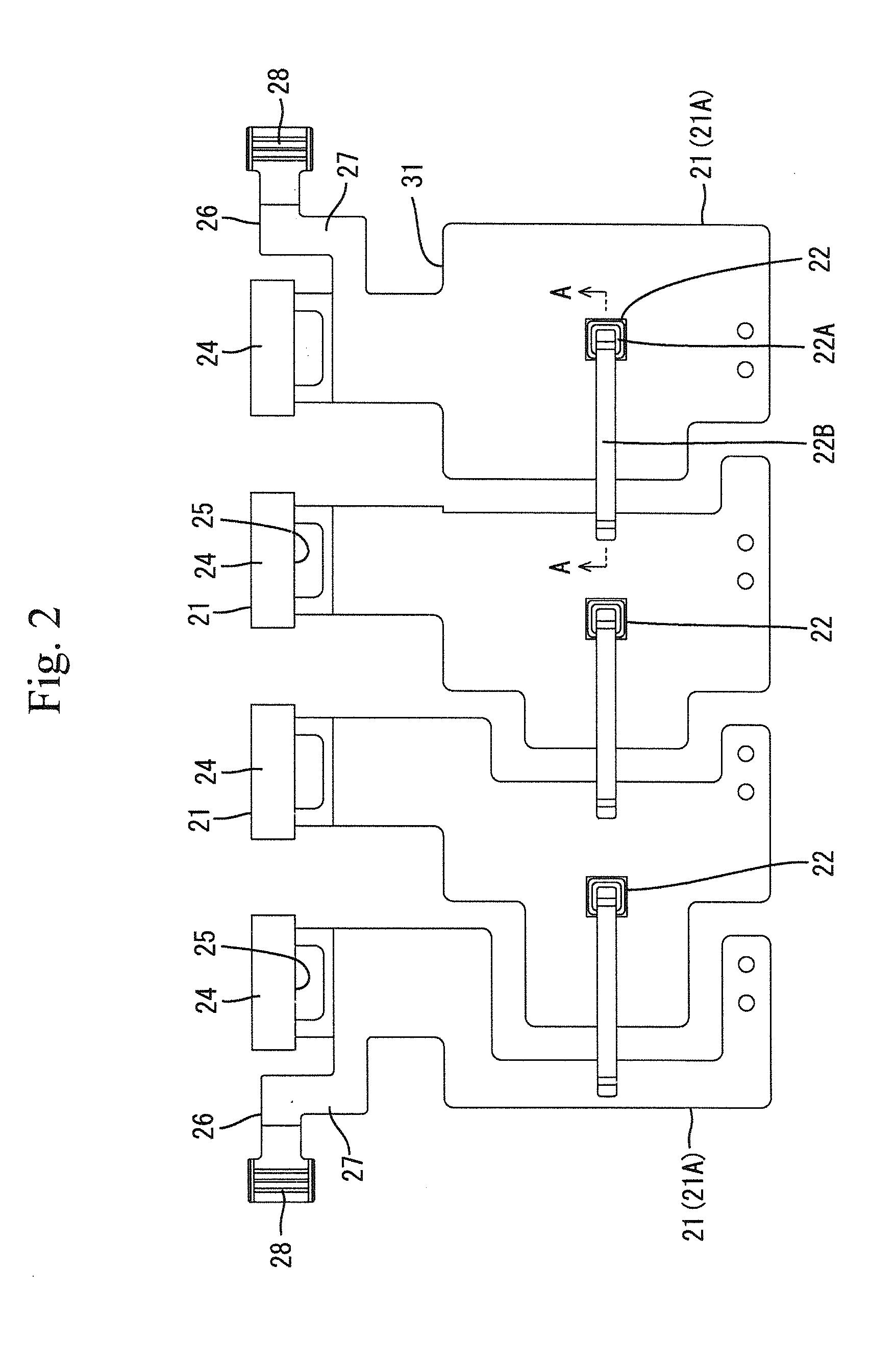
[0026]Each terminal board 21 is formed into the shape of a strip by the cutting or the like of an electrically conductive metal plate. Four terminal boards 21 are juxtaposed widthwise as shown in FIG. 2. Each terminal board 21 has a front end formed with a lead connecting portion 24 ...


PUM


Abstract

Provided is a terminal box for a solar cell module that has excellent heat radiation. The terminal box (10) is provided with multiple terminal boards (21), a reverse load bypass diode (22) that is connected to two corresponding terminal boards (21), a primary resin layer (23) that is attached to the diode (22) and covers the area around the diode (22), and a secondary resin layer (41) that is made from a resin different to that of the primary resin layer (23) and is adhered to parts other than the diode (22) and does not cover the area around the diode (22).

Description

BACKGROUND OF THE INVENTION[0001]1. Field of the Invention[0002]The present invention relates to a terminal box for use with solar cell module.[0003]2. Description of the Related Art[0004]Japanese Patent No. 3498945 discloses a conventional terminal box for use with a solar cell module. The disclosed terminal box comprises a plurality of terminal boards, bypass diodes for reverse load, each of which diodes is connected to two terminal boards, and a housing which houses the diodes and the terminal boards. The housing is filled with silicon resin after the terminal boards and the diodes have been housed. A cover is attached to the housing after the silicon resin has been cured.[0005]In the above-described terminal box, heat generated by the diodes is adapted to be released into the atmosphere after transfer through the silicon resin and the cover. However, since each diode is doubly resin-sealed by the silicon resin and the cover, there is a problem that the heat easily tends to stay ...

Claims


Application Information

Patent Timeline
IPC IPC(8): H05K5/02
CPCH05K5/02H02S40/345H02S40/34H05K7/20Y02E10/50
Inventor YOSHIKAWA, HIROYUKIHIGASHIKOZONO, MAKOTO
Owner SUMITOMO WIRING SYST LTD
Why Eureka
Try Eureka