

Welding condition determining method, and welding device
- Summary
- Abstract
- Description
- Claims
- Application Information
AI Technical Summary
Benefits of technology
Problems solved by technology
Method used
Image

Examples
first exemplary embodiment
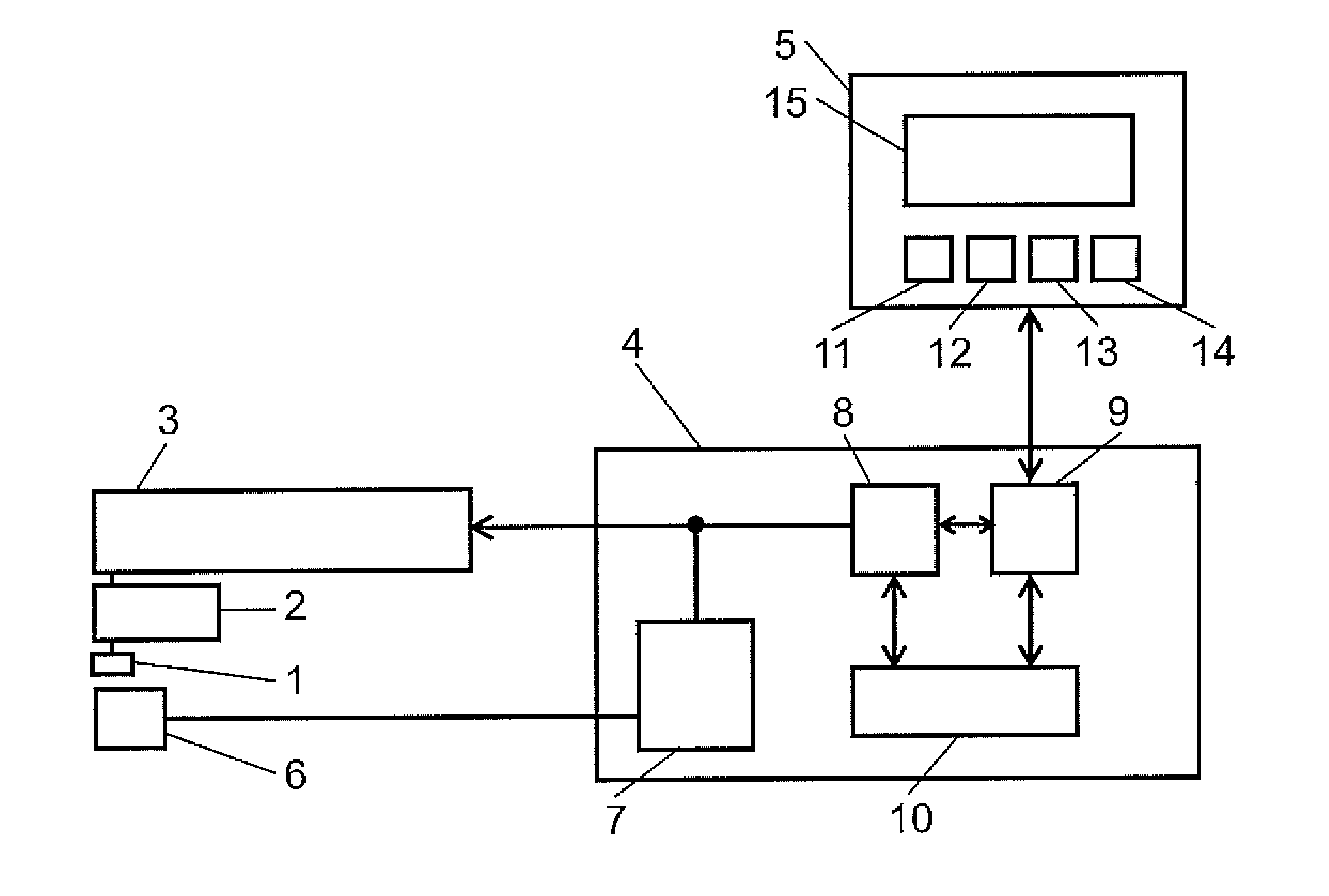
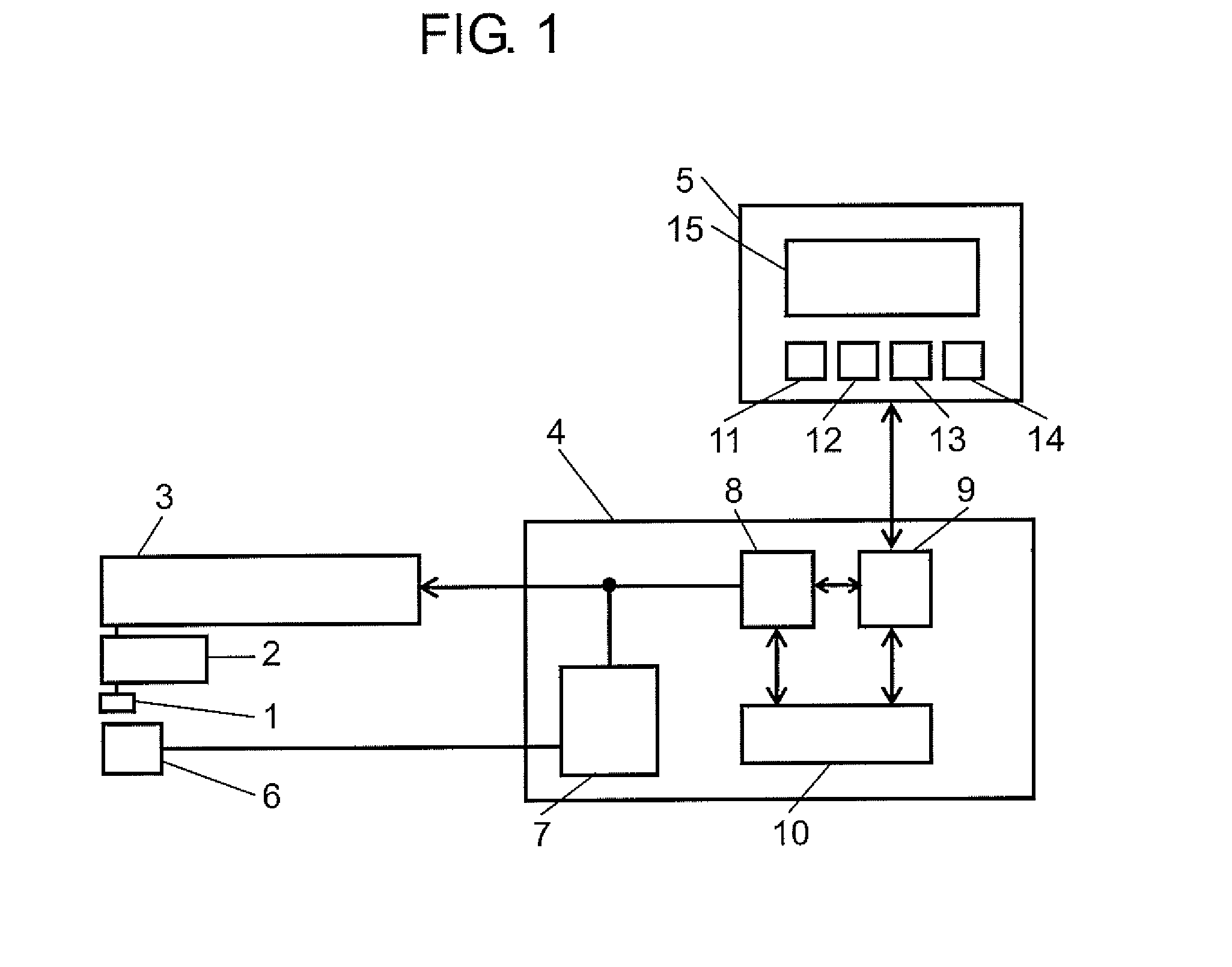
[0028]FIG. 1 shows a schematic configuration of a welding device according to a first exemplary embodiment of the present invention.
[0029]As shown in FIG. 1, the welding device of the present first exemplary embodiment, which is an arc welding device, includes manipulator 3, robot controller 4 for controlling the operation of manipulator 3, and setting device 5. Manipulator 3 moves welding torch 2, which holds electrode wire 1. Setting device 5 performs communications with robot controller 4 so as to set information to robot controller 4.
[0030]Robot controller 4 includes welding power supply 7, control unit 8, calculation unit 9, and storage unit 10. Welding power supply 7 supplies electric power to wire 1 so that welding is applied to object 6 to be welded. Control unit 8 controls the operations of manipulator 3 and welding power supply 7. Calculation unit 9 performs calculations for welding conditions. Storage unit 10 stores an operational program with which control unit 8 control...
second exemplary embodiment
[0098]FIG. 8 is a flowchart showing a procedure to determine recommended values for welding conditions in a second exemplary embodiment of the present invention.
[0099]The welding device and the method to determine welding conditions according to the present second exemplary embodiment will be described mainly with reference to FIG. 8. The same components as in the first exemplary embodiment are denoted by the same reference numerals, and hence the description thereof will be omitted. The present second exemplary embodiment differs from the first exemplary embodiment mainly in the processes after the recommended values for welding conditions are determined based on the object-to-be-welded information and the welding method information. In the first exemplary embodiment, the recommended value Sr is changed to a new value for the leg length, and then new recommended values for the other welding conditions are calculated. In the present second exemplary embodiment, on the other hand, th...
third exemplary embodiment
[0137]FIGS. 12A and 12B are first and second flowcharts, respectively, showing a procedure to determine recommended values for welding conditions in a third exemplary embodiment of the present invention.
[0138]The welding device and the method to determine welding conditions in the present exemplary embodiment will be described with reference to FIGS. 12A and 12B. The same components as in the first and second exemplary embodiments are denoted by the same reference numerals, and hence the description thereof will be omitted. The present exemplary embodiment differs from the first and second exemplary embodiments mainly in the processes after the recommended values for welding conditions are determined based on the object-to-be-welded information and the welding method information. In the first exemplary embodiment, the recommended value Sr is changed to a new value for the leg length, and then new recommended values for the other welding conditions are calculated. In the second exemp...
PUM
| Property | Measurement | Unit |
|---|---|---|
| Length | aaaaa | aaaaa |
| Thickness | aaaaa | aaaaa |
| Diameter | aaaaa | aaaaa |
Abstract
Description
Claims
Application Information