Electrical impedance tomography device and process

a tomography device and electric impedance technology, applied in the field of electric impedance tomography devices, can solve the problems of small errors in the measured boundary voltage, low voltage, and inability to detect the difference between the two, and achieve the effect of small errors and large errors

a tomography device and electric impedance technology, applied in the field of electric impedance tomography devices, can solve the problems of small errors in the measured boundary voltage, low voltage, and inability to detect the difference between the two, and achieve the effect of small errors and large errors

US20130002264A1Active Publication Date: 2013-01-03DRAGERWERK AG

Image

  • Electrical impedance tomography device and process
  • Electrical impedance tomography device and process
  • Electrical impedance tomography device and process

Examples


Embodiment Construction

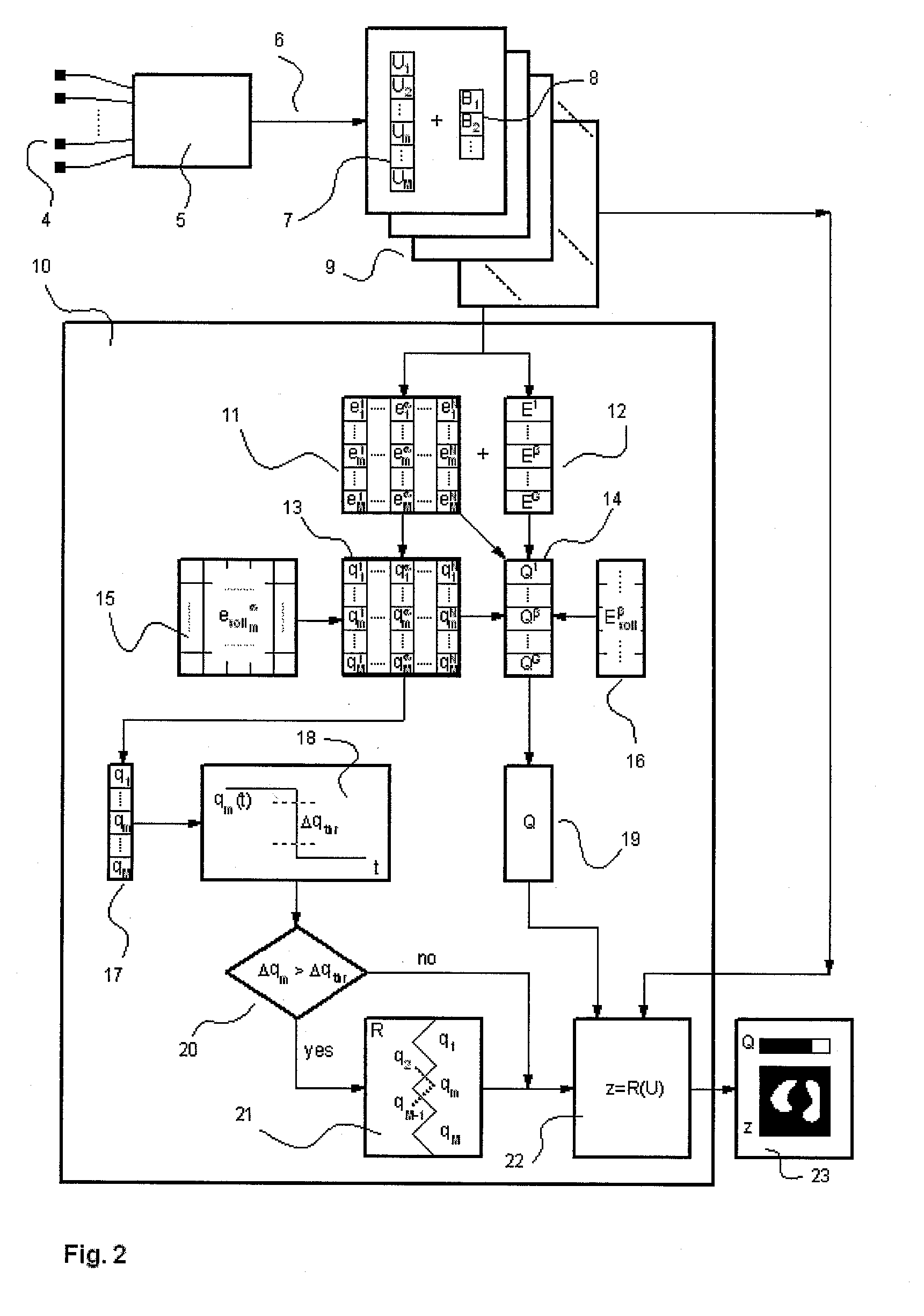
[0024]Referring to the drawings in particular, the present invention creates an EIT device and process with the following design features, corresponding to FIG. 2 and FIG. 3

[0025]1. The voltages (7) of all M measuring channels are analyzed continuously for possible interferences. This can be done by comparing α=1 . . . N properties emα(Um) (11), the measured voltages of all m=1 . . . M channels relative to expected desired values and / or desired ranges esollmα (15). The desired range can be derived, for example, from device parameters and / or from theoretical considerations such as reciprocity and / or by analyzing a large data set of EIT measurements from hospitals and / or laboratory tests with specific interferences. Examples of measurable and derivable properties of measured voltages are, of course, the SNR determined, on the one hand, but also freak values of voltages or changes of these voltages, mean value, phase and real and imaginary part of the voltage, determined crosstalk esti...


PUM


Abstract

An EIT device has a plurality of electrodes (4) that can be arranged on a body in order to reconstruct the impedance distribution of the body with a reconstruction algorithm. The control unit (10) of the EIT device is set up by suitable programming to continuously determine at least one property (e1, . . . , eM) each from the measured signals (U1, . . . , UM) of all measuring channels and to correct measured signals of the measuring channels on the basis of the properties or to adapt the reconstruction algorithm on the basis of the properties.

Description

CROSS REFERENCE TO RELATED APPLICATIONS[0001]This application claims the benefit of priority under 35 U.S.C. §119 of German Patent Application DE 10 2011 106 405.6 filed Jul. 2, 2011, the entire contents of which are incorporated herein by reference.FIELD OF THE INVENTION[0002]The present invention pertains to an electrical impedance tomography device with a plurality of electrodes, which can be arranged on a body, with control and measuring circuits to feed alternating current or alternating voltage to the electrodes and to receive voltage or current signals received from the electrodes as measured signals, and with a control unit, which is connected to the control and measuring circuits and is set up by suitable programming to supply one electrode pair each with an alternating current or with an alternating voltage, to receive the voltage signal or current signal of each electrode pair from all other electrode pairs as a measured signal of a measuring channel and to have the feedi...

Claims


Application Information

Patent Timeline
03 Jan 2013
Publication
US20130002264A1
IPC
G01R27/00
CPC
A61B5/08; A61B5/0536; G06T7/0012; G06T7/0016; G06T7/30
Inventors
GARBER, YVO