Method and device for forming surface processing data

a surface processing and data technology, applied in the field of surface processing data, can solve the problems of unevenness of the grain on the mold, difficult to form the same shape repeatedly, and difficulty in representing fine shapes, etc., and achieve the effect of small amount of data to be processed and small sample data siz

Inactive Publication Date: 2013-01-03
CALSONIC KANSEI CORP +1
View PDF2 Cites 9 Cited by
  • Summary
  • Abstract
  • Description
  • Claims
  • Application Information

AI Technical Summary

Benefits of technology

[0054]In the present invention described above, the product shape data is first converted into a polygon mesh and then processed as curved surface data having no thickness, whereby the amount of data to be processed can be made small.
[0055]The polygon mesh is divided into regions, and a texture that is connected to the texture in the previously mapped region while having predetermined smoothness is mapped in an adjacent region; this process is repeated sequentially to map the texture in the entire polygon mesh, whereby through the selection of the fineness of the division of regions, there is provided an effect that a good-looking grain with few distortions can be given even in the case of a product shape whose surface cannot be developed.
[0056]Furthermore, since the synthesis of the new texture is advanced in each divided region, the texture data is not required to have a size covering the entire surface of the product; hence, a relatively small size of sample data should only be prepared.

Problems solved by technology

In the above-mentioned etching method, shapes are formed by corrosion; hence, the method is also applicable to metal molds for producing large products at low cost; however, the method is difficult to represent fine shapes and also difficult to form the same shape repeatedly.
Furthermore, in the case that a grain is formed in the normal direction of the curved surface of a product, if so-called undercut, in which the removing direction of the product intersects with the curved surface of the product on a surface along the opening direction of an injection molding metal mode, occurs, the unevenness of the grain on the mold interferes with the unevenness of the grain transferred to a molded product when the molded product is removed; if the molded product is forcibly removed from the metal mold, the grain on the molded product is damaged.
Moreover, in the case that a grain pattern is given to a metal mold by the etching method, the depth of the grain cannot be changed continuously; if the depth is made shallow stepwise, the joints thereof are exposed and the appearance is damaged.
Besides, due to the result that the method requires many processes, the work period is long and the cost is high; hence, only the special manufacturers having dedicated facilities can adopt the electroforming method.
What's more, the shape and size of the grain are determined by the grain on the resin sheet that is bonded when the master model is formed, and it is thus difficult to provide additional patterns at any desired portions later and also difficult to expand or reduce the grain patterns.
Still further, both the methods are disadvantageous in that chemical solution processing or the like is required.

Method used


Image

  • Method and device for forming surface processing data
  • Method and device for forming surface processing data
  • Method and device for forming surface processing data

Examples


Embodiment Construction

[0097]An embodiment according to the present invention will be described below.

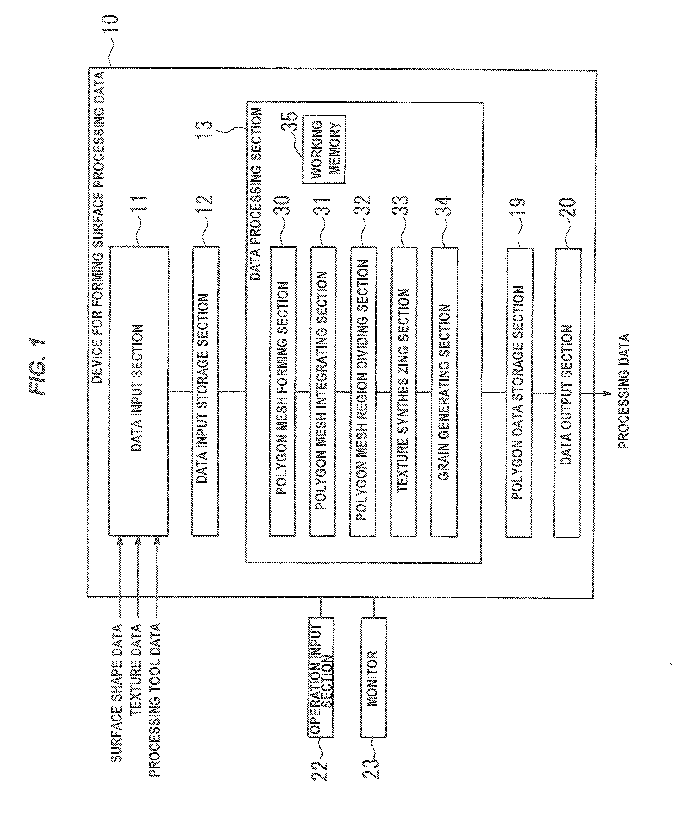
[0098]FIG. 1 is a block diagram showing a configuration of a device for forming surface processing data according to an embodiment.

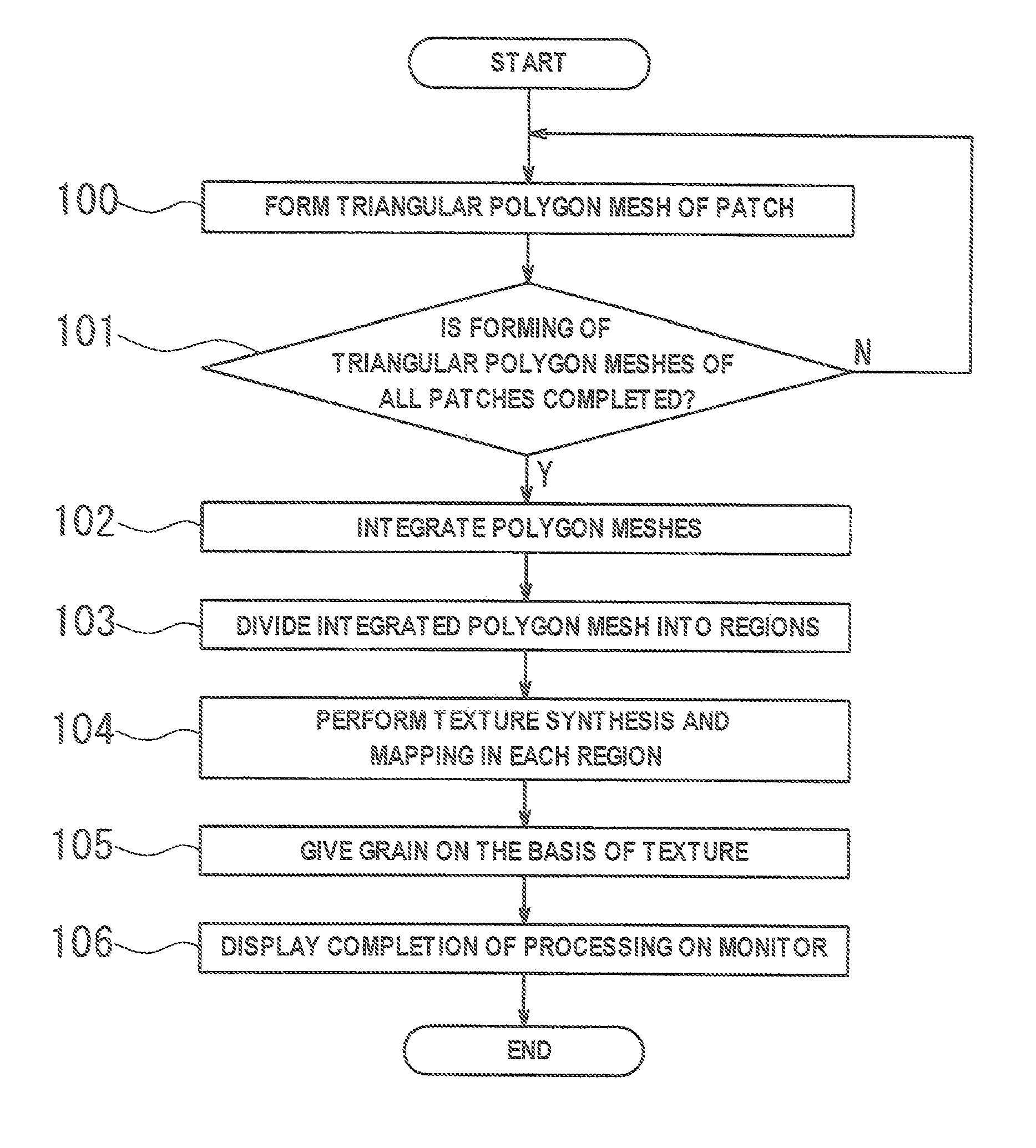
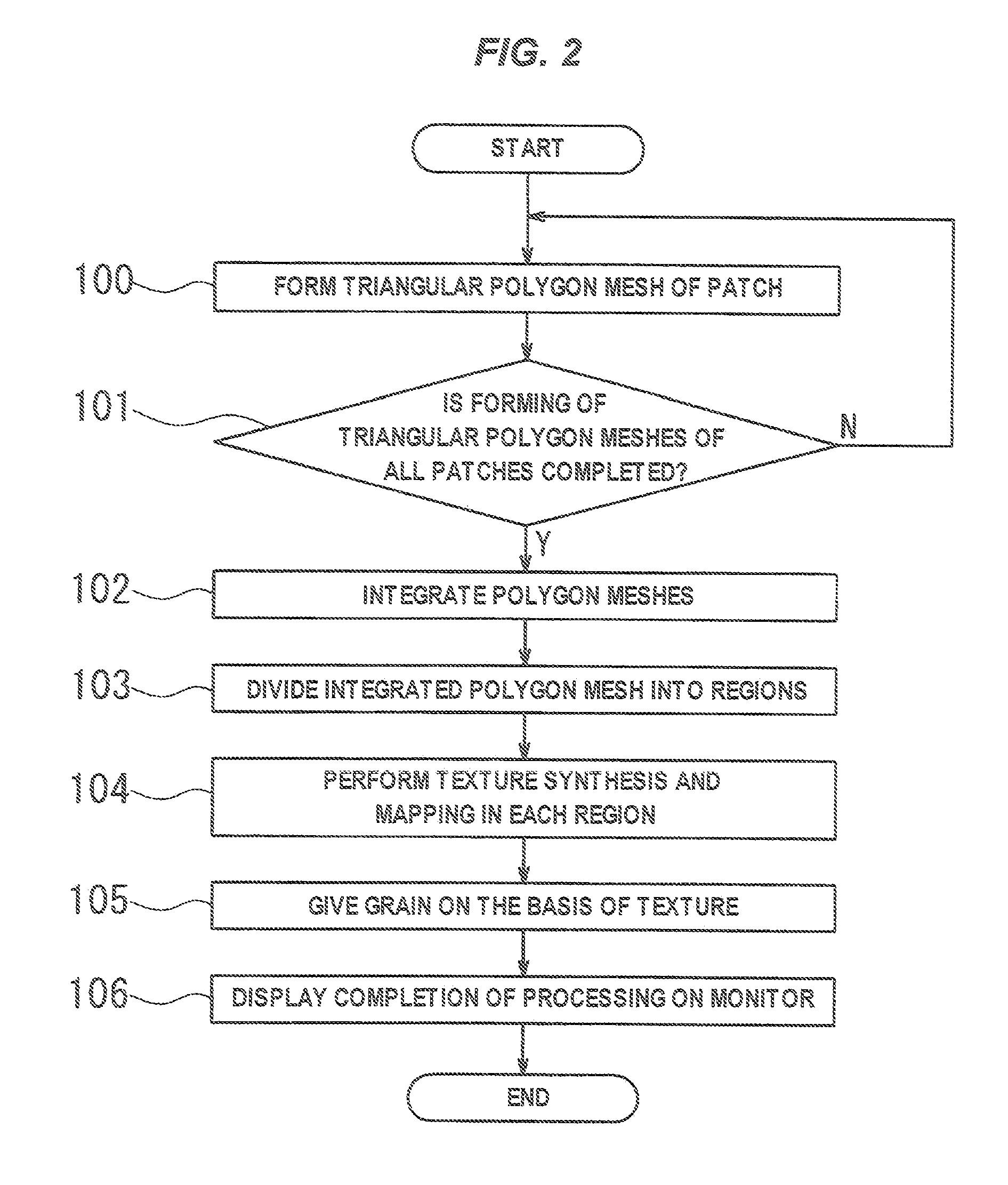
[0099]A device for forming surface processing data 10 has a data input section 11 for inputting the surface shape of a product, the texture data of a grain and processing tool data; an input data storage section 12; and a data processing section 13 for generating polygon data in which a grain shape is given to the curved surface of the product on the basis of the data stored in the input data storage section 12; a polygon data storage section 19 for storing the generated polygon data; and a data output section 20 for outputting the polygon data as processing data from the polygon data storage section 19.

[0100]An operation input section 22 equipped with a keyboard, a jog lever, etc. and a monitor 23 capable of displaying image data are connected to the device for forming surfac...


PUM


Abstract

A polygon-meshed surface of a product is divided into regions, and a texture GA is mapped in an initial region A. The boundary line of an adjacent region B is multiplexed outward, and an overlapped region D is provided between the initial region and the adjacent region, and a region X to be processed is projected onto a two-dimensional plane and a texture GB is allocated. An optimal boundary line FS in which the difference between the pixel values of the textures GA and GB becomes minimal in the overlapped region is obtained, and the texture GB is mapped in the region X being processed so that the texture is connected to the texture GA at the optimal boundary line. The apexes of the polygon mesh displaced on the basis of the textures mapped in all the regions are connected to obtain grain-given polygon data.

Description

TECHNICAL FIELD[0001]The present invention relates to a method and a device for forming a grain pattern on the surface of a resin product.BACKGROUND ART [0002]On the surfaces of home electric appliances, stationery products or automotive interior products, grains are formed for various purposes, such as improvements in appearance and tactile sensation, glare proofing, and anti-skidding. Various fine patterns, such as leather-grain, wood-grain, rock-grain, sand-grain, pear-grain, and geometric patterns, are adopted as grain patterns. For the purpose of forming these grains on the surfaces of resin products, grain patterns are conventionally given on metal molds, for example, by an etching method or an electroforming method.[0003]In the above-mentioned etching method, shapes are formed by corrosion; hence, the method is also applicable to metal molds for producing large products at low cost; however, the method is difficult to represent fine shapes and also difficult to form the same...

Claims


Application Information

Patent Timeline
Patent Type & Authority Applications(United States)
IPC IPC(8): G06T15/04
CPCG06T15/04Y02T10/82G06T17/20
Inventor KIKUTA, MAMORUMIURA, KENJIRO
Owner CALSONIC KANSEI CORP
Why Eureka
Try Eureka