Photo mask unit comprising a photomask and a pellicle and a method for manufacturing the same

a technology of photomask and pellicle, which is applied in the field of photomask units comprising photomasks, can solve the problems of difficult mounting of pellicle frames on photomasks, and achieve the effect of reliably preventing the flatness of a photomask from being lowered

Inactive Publication Date: 2013-01-03
SHIN ETSU CHEM IND CO LTD
View PDF8 Cites 9 Cited by
  • Summary
  • Abstract
  • Description
  • Claims
  • Application Information

AI Technical Summary

Benefits of technology

[0017]It is therefore an object of the present invention to provide a photomask unit comprising a pellicle and a photomask, the photomask unit being suitable for forming a microscopic pattern of 32 nm or smaller on a photoresist film using an EUV exposure technique and being able to reliably prevent the flatness of a photomask from being lowered.
[0038]Further, according to the present invention, it is possible to provide a method for fabricating a photomask unit comprising a photomask and a pellicle, the photomask unit being suitable for forming a microscopic pattern of 32 nm or smaller on a photoresist film using an EUV exposure technique and being able to reliably prevent the flatness of a photomask from being lowered.

Problems solved by technology

As a result, in the case of employing an agglutinant agent containing an organic material, since an outgas is generated from the agglutinant agent containing the organic material, it is difficult to mount a pellicle frame on a photomask using an agglutinant agent containing an organic material and it is necessary to avoid as practicably as possible using an agglutinant agent containing an organic material in the vicinity of a photomask.

Method used


Image

  • Photo mask unit comprising a photomask and a pellicle and a method for manufacturing the same
  • Photo mask unit comprising a photomask and a pellicle and a method for manufacturing the same
  • Photo mask unit comprising a photomask and a pellicle and a method for manufacturing the same

Examples


working example no.1

WORKING EXAMPLE NO. 1

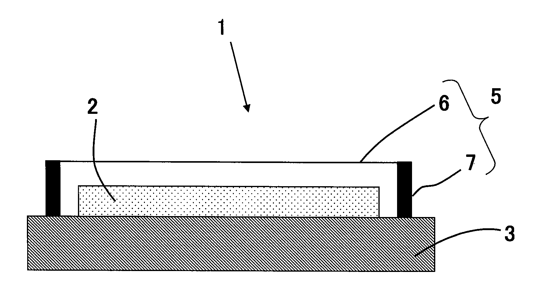
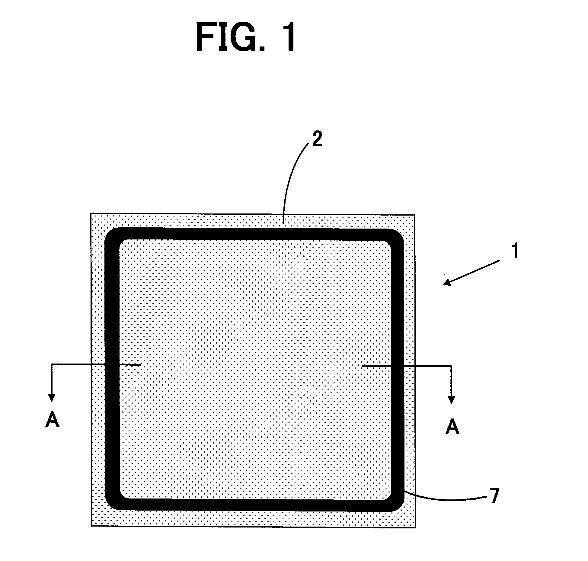
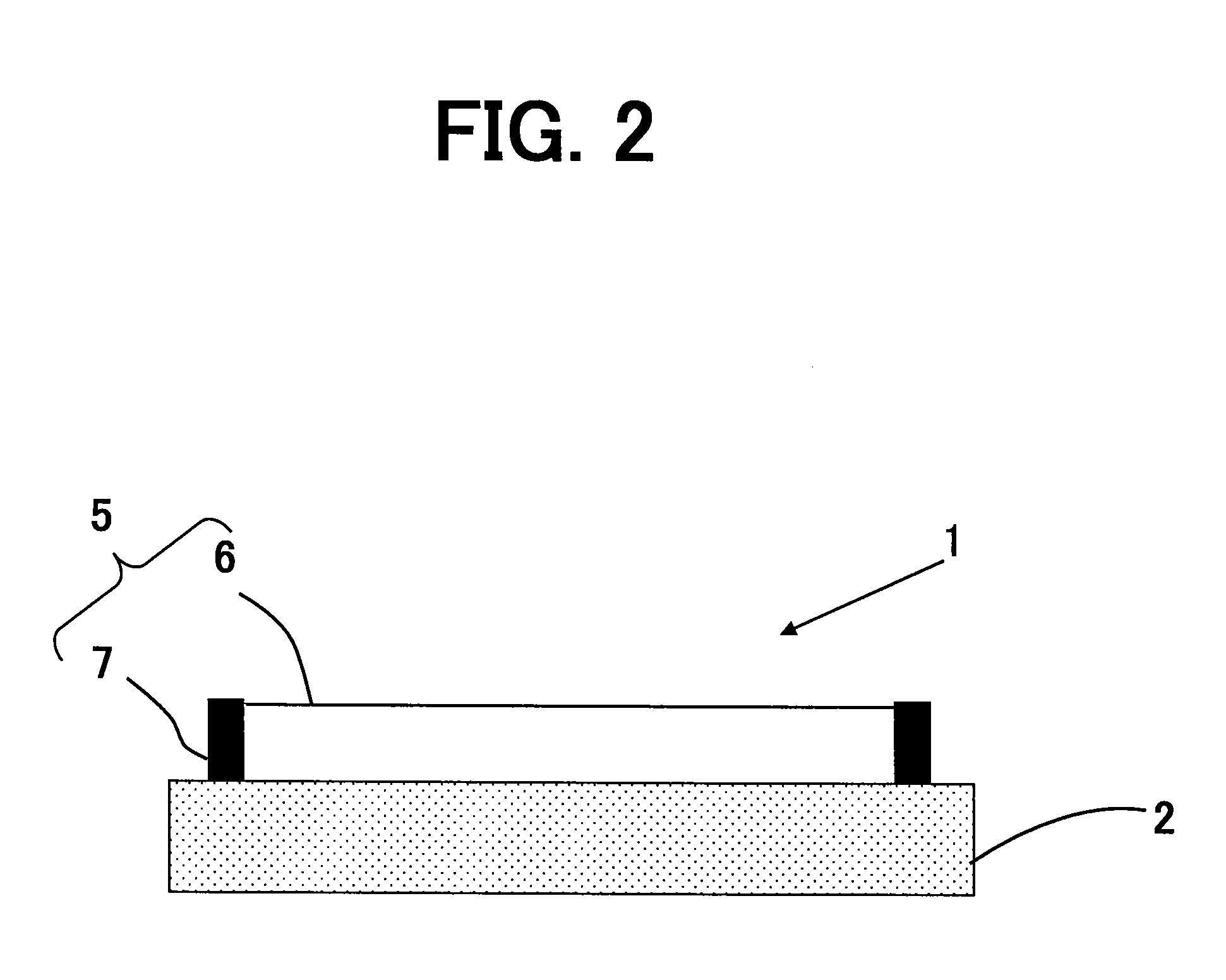
[0062]A square shaped photomask substrate whose one side length was 152 mm and thickness was 6 mm and which was made of quartz was prepared and a chromium film was evaporated on one surface of the photomask substrate and the other surface of the photomask substrate was fixed onto a photomask stage by an electrostatic chuck.

[0063]Then, a rectangle shaped pellicle frame whose inner frame length was 160 mm, outer frame length was 166 mm and wall thickness was 3 mm and which was made of aluminum was prepared and the pellicle frame was fixed by an electrostatic chuck onto the photomask stage at a region outside of a region of the photomask stage onto which the photomask substrate was fixed, thereby fabricating a photomask unit.

[0064]Next, in order to simulate the behavior of the photomask unit when it would be subjected to a high speed scanning operation in an actual manufacturing line, the photomask stage was vibrated for ten minutes so that acceleration of about 5 ...

working example no.2

WORKING EXAMPLE NO. 2

[0066]A square shaped photomask substrate whose one side length was 152 mm and thickness was 6 mm and which was made of quartz was prepared and a chromium film was evaporated on the one surface of the photomask substrate and the other surface of the photomask substrate was fixed onto a photomask stage by an electrostatic chuck.

[0067]Then, a pellicle frame made of aluminum whose inner frame length was 160 mm, outer frame length was 166 mm and wall thickness was 3 mm was prepared and the pellicle frame was fixed by a mechanical clamp onto the photomask stage at a region outside of a region of the photomask stage onto which the photomask substrate was fixed, thereby fabricating a photomask unit.

[0068]Next, in order to simulate the behavior of the photomask unit when it would be subjected to a high speed scanning operation in an actual manufacturing line, the photomask stage was vibrated for ten minutes so that acceleration of about 5 G was applied to the photomask ...

working example no.3

WORKING EXAMPLE NO. 3

[0070]A square shaped photomask substrate whose one side length was 152 mm and thickness was 6 mm and which was made of quartz was prepared and a chromium film was evaporated on the one surface of the photomask substrate and the other surface of the photomask substrate was fixed onto a photomask stage by an electrostatic chuck.

[0071]Then, a pellicle frame whose inner frame length was 160 mm, outer frame length was 166 mm and wall thickness was 3 mm and which was made of aluminum was prepared and the pellicle frame was fixed by a silicone agglutinant agent onto the photomask stage at a region outside of a region of the photomask stage onto which the photomask substrate, thereby fabricating a photomask unit.

[0072]Next, in order to simulate the behavior of the photomask unit when it would be subjected to a high speed scanning operation in an actual manufacturing line, the photomask stage was vibrated for ten minutes so that acceleration of about 5 G was applied to ...


PUM

PropertyMeasurementUnit
dominant wavelengthaaaaaaaaaa
wavelengthaaaaaaaaaa

Abstract

It is an object of the present invention to provide a photomask unit suitable for forming a microscopic pattern of 32 nm or smaller on a photoresist film using the EUV exposure technique and being able to reliably prevent the flatness of a photomask from being lowered. The photomask unit 1 according to the present invention includes a pellicle membrane 6, a pellicle frame 7 onto one surface of which a region of the pellicle membrane 6 in the vicinity of side portions of the pellicle membrane 6 is fixed, a photomask 2 and a stage 3 onto one surface of which the photomask 2 and the pellicle frame 7 are fixed, and the pellicle frame 7 is fixed onto the stage 3 at a region outside of a region of the stage 3 onto which the photomask 2 is fixed.

Description

CROSS-REFERENCES TO RELATED APPLICATIONS[0001]This application is a continuation-in-part of and claims priority to International Patent Application No. PCT / JP2011 / 055602 filed on Oct. 3, 2011 and is related to and claims priority to Japanese Patent Application No. JP2010-086368 filed on Apr. 2, 2010, the entire content of both patent applications is hereby incorporated by reference.FIELD OF THE INVENTION[0002]The present invention relates to a method for fabricating a photomask unit comprising a pellicle for lithography for use as a dustproof cover for an exposure stencil such as a photomask, a reticle or the like (hereinafter collectively referred to as “photomask” in this specification) when a semiconductor device such as a large-scale integrated circuit, a very-large-scale integrated circuit (LSI) or the like, or a liquid crystal display panel is to be manufactured and a photomask, and particularly relates to a photomask unit and a method for fabricating a photomask unit suitable...

Claims


Application Information

Patent Timeline
Patent Type & Authority Applications(United States)
IPC IPC(8): G03B27/58B23P11/00G03F1/24G03F1/62G03F1/64
CPCG03F1/24Y10T29/49826G03F1/64G03F1/62H01L21/0274
Inventor AKIYAMA, SHOJIKUBOTA, YOSHIHIRO
Owner SHIN ETSU CHEM IND CO LTD
Why Eureka
Try Eureka