
System and Method for Non-Uniform Bit Allocation in the Quantization of Channel State Vectors

a channel state vector and bit allocation technology, applied in the field of wireless communication, can solve the problems of low reliability of transmission rate, low bandwidth of feedback channel, and inability to standardized method the quantization of pmi for a large number of transmit antennas, so as to reduce channel state information resolution and low loss. , the effect of high loss

Active Publication Date: 2013-01-03
FUTUREWEI TECH INC
View PDF1 Cites 18 Cited by
  • Summary
  • Abstract
  • Description
  • Claims
  • Application Information

AI Technical Summary

Benefits of technology

The technology described in this patent allows for non-uniform allocation of bits for the quantization of channel state vectors, which leads to additional resolution in low loss situations and reduces resolution in high loss situations. This provides greater control in beamforming and allows for better use of the additional resolution. Additionally, a constant number of states per stage is presented with a trellis structure, which simplifies trellis decoding and encoding. This efficient quantization of channel state vectors reduces computational requirements on receivers, allowing for the use of less powerful and lower power consuming processors. This results in lower costs and an extended battery life for receivers.

Problems solved by technology

However, due to overall bandwidth utilization issues, a feedback channel usually has limited bandwidth as well as a low reliable transmission rate.
Furthermore, there is no standardized method for quantizing the PMI for a large number of transmit antennas.
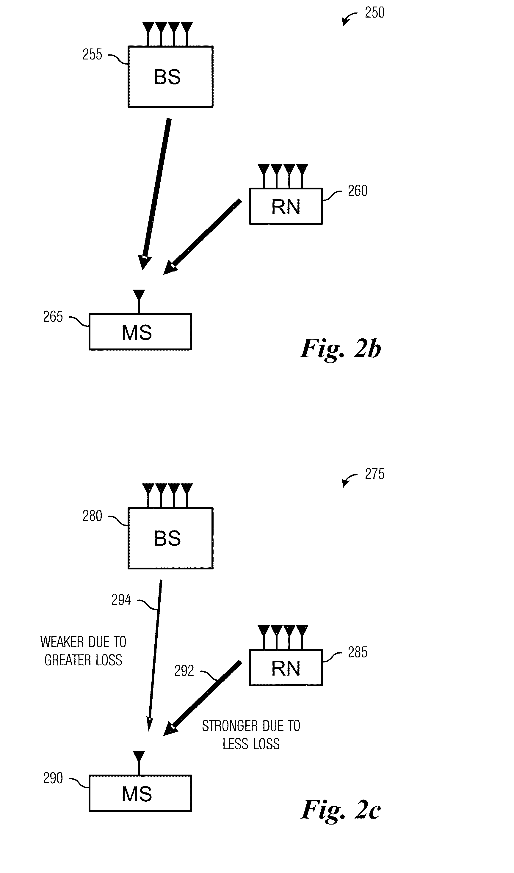
Furthermore, transmissions from different transmission points may experience different losses, such as path loss, fading, shadowing, and so forth, which may mean that transmissions originally transmitted at substantially the same power level may arrive at their destinations at different energy levels.

Method used


Image

  • System and Method for Non-Uniform Bit Allocation in the Quantization of Channel State Vectors
  • System and Method for Non-Uniform Bit Allocation in the Quantization of Channel State Vectors
  • System and Method for Non-Uniform Bit Allocation in the Quantization of Channel State Vectors

Examples


Embodiment Construction

[0033]The making and using of the embodiments are discussed in detail below. It should be appreciated, however, that the present invention provides many applicable inventive concepts that can be embodied in a wide variety of specific contexts. The specific embodiments discussed are merely illustrative of specific ways to make and use the invention, and do not limit the scope of the invention.

[0034]The embodiments will be described in a specific context, namely a MIMO wireless communications system adherent to the 3GPP LTE technical standards. The invention may also be applied, however, to other wireless communications systems MIMO wireless communications system, such as LTE-Advanced compliant systems, as well as wireless communications systems that allow MIMO operations with a large number of transmit antennas and / or cooperative (or joint) MIMO operation with multiple base stations and / or relay nodes.

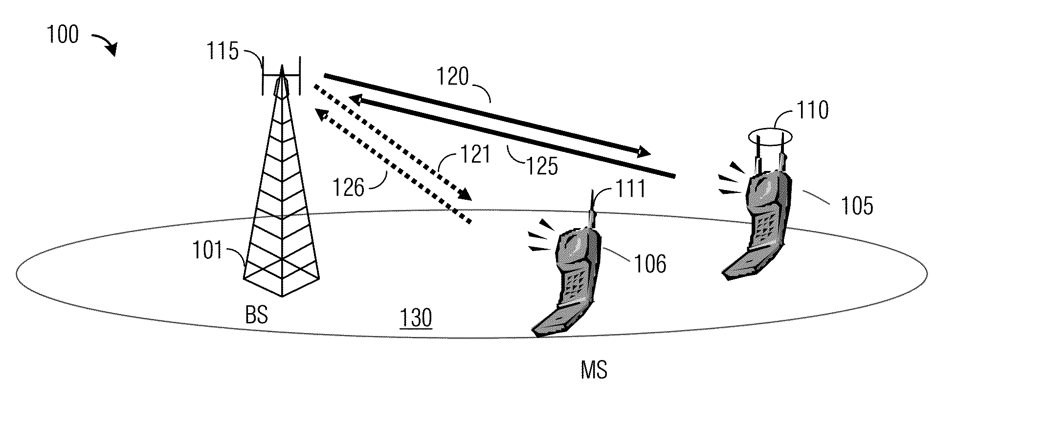
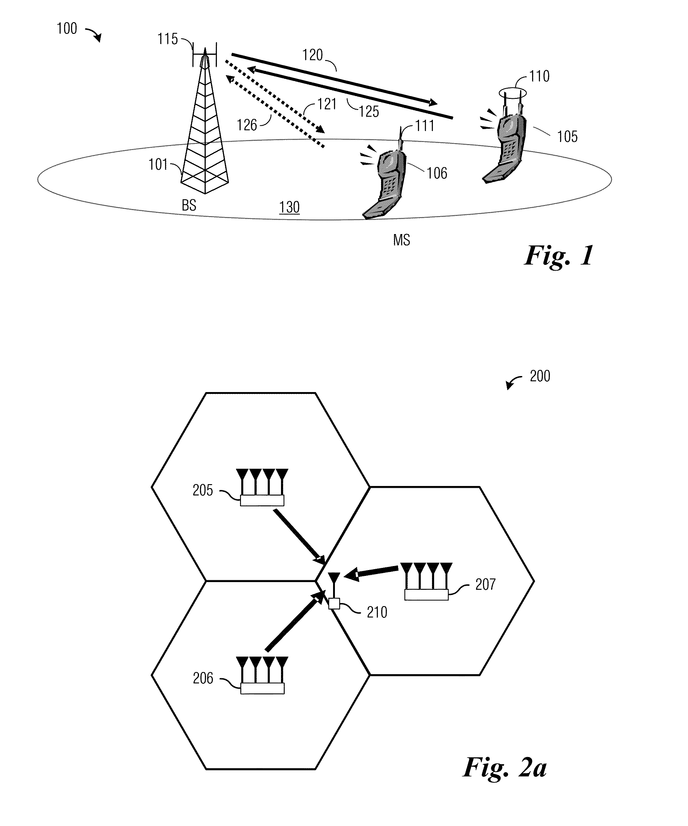
[0035]FIG. 1 illustrates a wireless communications system 100. Wireless communicati...


PUM


Abstract

A system and method for non-uniform bit allocation in the quantization of channel state vectors is provided. A method for communications node operation includes receiving a bit-allocation profile for use in quantizing channel state information, measuring a communications channel between the communications node and a controller, generating channel state information based on the measurement, computing a bit representation of the channel state information, transmitting the bit representation to the controller, and receiving a transmission from the controller. The computing makes use of quasi-tail-biting trellis decoding, and the computing is based on the bit-allocation policy. The transmission makes use of the channel state information transmitted by the communications node.

Description

[0001]This application is a continuation of U.S. patent application Ser. No. 12 / 633,418, entitled “System and Method for Non-Uniform Bit Allocation in the Quantization of Channel State Vectors,” filed on Dec. 8, 2009, which application is hereby incorporated herein by reference.TECHNICAL FIELD[0002]The present invention relates generally to wireless communications, and more particularly to a system and method for non-uniform bit allocation in the quantization of channel state vectors.BACKGROUND[0003]Generally, in a multiple input, multiple output (MIMO) wireless communications system, it is beneficial for a transmitter to have some knowledge of channel state information of a communications channel between itself and a receiver. One form of channel state information, as implemented in technical standards such as the Third Generation Partnership Project (3GPP) Long Term Evolution (LTE), is a combination of a precoding matrix index (PMI), a channel quality index (CQI) and a rank indica...

Claims


Application Information

Patent Timeline
Patent Type & Authority Applications(United States)
IPC IPC(8): H04L23/02H04B17/00
CPCH04L1/0026H04L1/0047H04L1/20H04L1/0059H04L1/0054
Inventor AU-YEUNG, CHUN KINSANAYEI, SHAHAB
Owner FUTUREWEI TECH INC
Learn More