Eureka AIR delivers breakthrough ideas for toughest innovation challenges, trusted by R&D personnel around the world.

Negative-Electrode Plate and Cylindrical Cell Including Same

Inactive Publication Date: 2013-01-03
FDK CORP
View PDF2 Cites 4 Cited by
  • Summary
  • Abstract
  • Description
  • Claims
  • Application Information

AI Technical Summary

Benefits of technology

The present invention provides a cylindrical cell with improved efficiency in manufacture. This is achieved through the use of a second negative-electrode part with lower density and higher permeability to the electrolyte, which allows for easier permeation of the electrolyte during manufacture. Additionally, the second negative-electrode part allows for increased production capacity without reducing the overall capacity of the cell. The invention also includes a design for the electrodes that reduces the likelihood of damage during formation, resulting in a more flexible and efficient electrode body. Overall, the invention increases the volumetric efficiency and capacity of the cylindrical cell.

Problems solved by technology

The electrolyte thus fills the outer can by gradually permeating the separator, positive-electrode plate and negative electrode plate, from the center to the periphery of the electrode body, where if the electrolyte does not satisfactorily permeate the electrode body, it follows that the whole electrode body fails to be uniformly activated, possibly resulting in deteriorated cycle performance and high-rate discharge performance.
However, the electrode body including the negative-electrode plate designed such that the first turn forming the innermost circumference of the electrode body has an increased negative-electrode active material density, as in the cell disclosed in Japanese Patent Application Laid-open No. 2004-303494, for example, exhibits a greatly-decreased permeability to the electrolyte, resulting in increased time taken to put a required amount of the electrolyte into the outer can and let it permeate the electrode body, and thus, decreased efficiency of manufacture of the cylindrical cell.

Method used


Image

  • Negative-Electrode Plate and Cylindrical Cell Including Same
  • Negative-Electrode Plate and Cylindrical Cell Including Same
  • Negative-Electrode Plate and Cylindrical Cell Including Same

Examples


Embodiment Construction

[0029]With reference to the drawings attached, an embodiment of the present invention will be described below.

Structure of Nickel-Hydrogen Secondary Cell

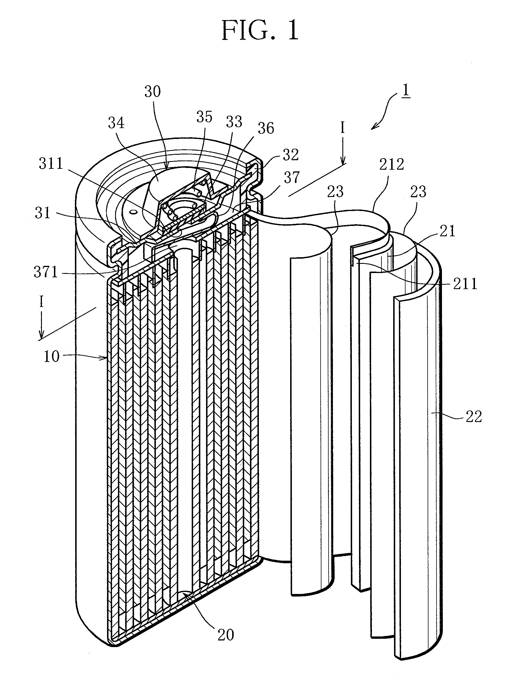
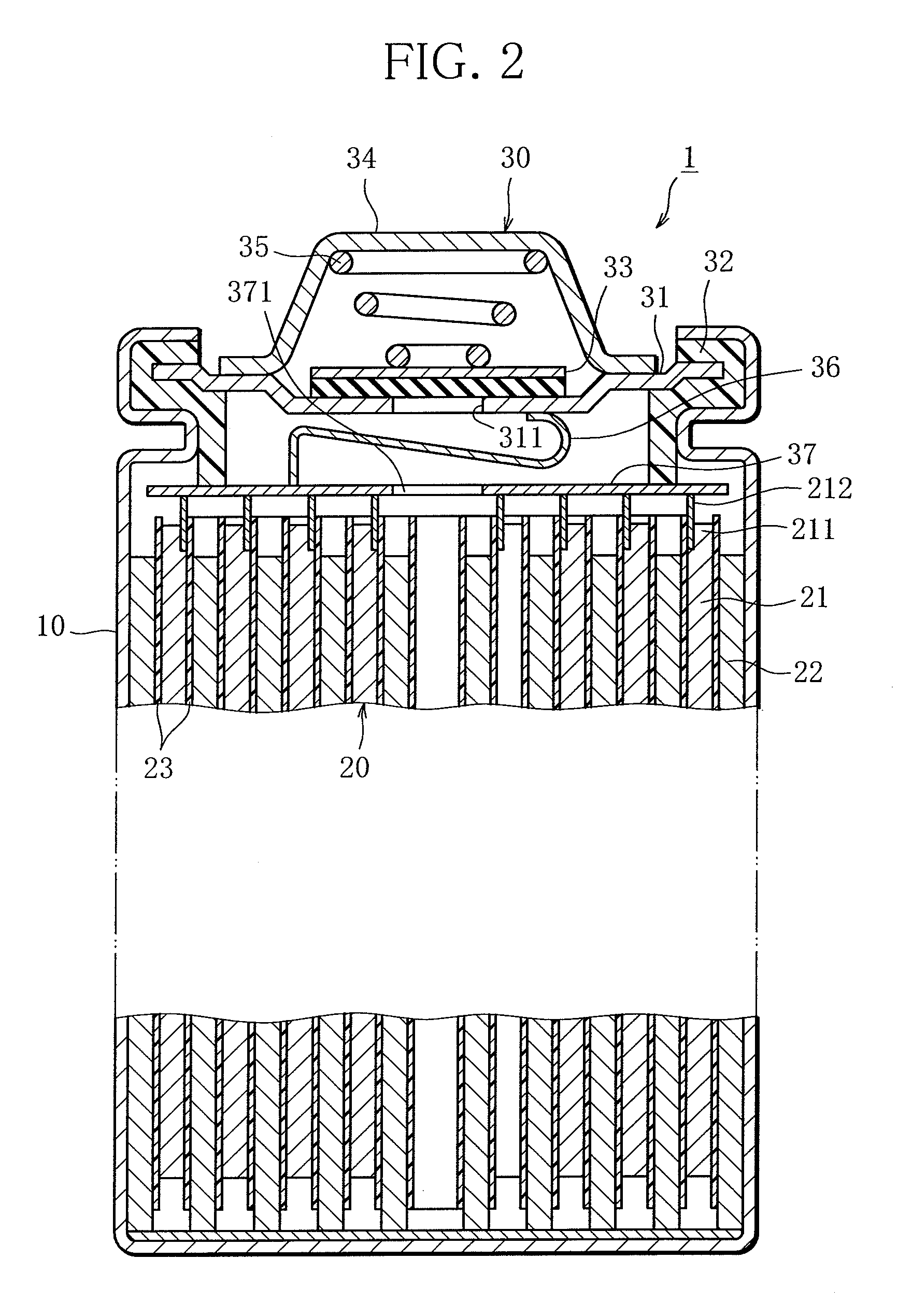
[0030]Referring to FIGS. 1 to 3, structure of a nickel-hydrogen secondary cell 1 will be described.

[0031]FIG. 1 is a perspective view showing a vertical cross-section of the nickel-hydrogen secondary cell 1, FIG. 2 a plan view showing a transverse cross-section of the nickel-hydrogen secondary cell 1, and FIG. 3 a transverse cross-sectional view of the nickel-hydrogen secondary cell 1 along line I-I indicated in FIG. 1.

[0032]The cylindrical nickel-hydrogen secondary cell 1 exemplifying the “cylindrical cell” comprises an outer can 10, an electrode body 20 and a lid structure 30. The outer can 10 is an electrically-conductive bottomed cylindrical member open at the top. The electrode body 20 is formed by stacking a positive-electrode plate 21 and a negative-electrode plate 22 with a separator 23 interposed between and rolling them in...


PUM


Abstract

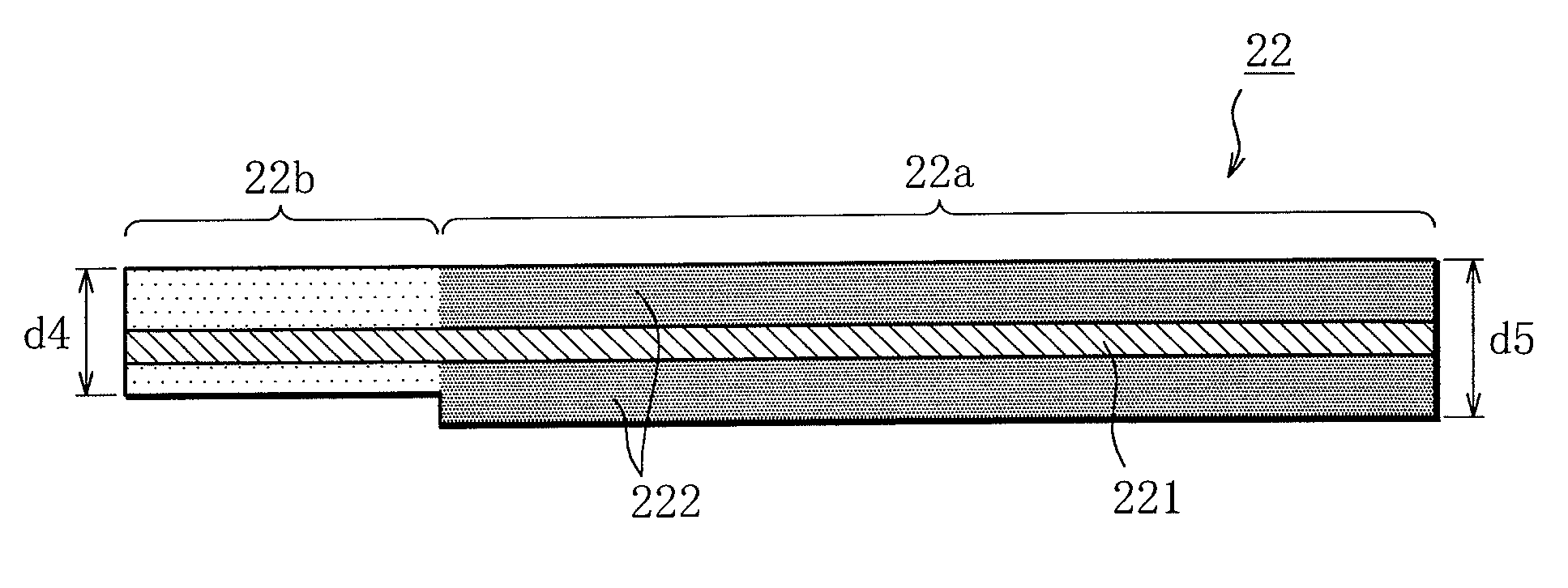
A negative-electrode plate 22 for use in a cylindrical cell, intended to be laid over a positive-electrode plate 21 with a separator 23 interposed between and rolled to form a cylindrical electrode body 20, with the positive-electrode plate 21 inside, the electrode body being arranged in a bottomed cylindrical outer can 10 to form the cylindrical cell, comprises a first negative-electrode part 22a which is to face the positive-electrode plate 21 on either side, with the separator 23 between, when formed into the electrode body 20, and a second negative-electrode part 22b which is to form the innermost circumference of the electrode body 20 and face the positive-electrode plate 21 only on one side, with the separator 23 between, when formed into the electrode body 20, the second negative-electrode part 22b being lower in negative-electrode active material density than the first negative-electrode part 22a.

Description

BACKGROUND OF THE INVENTION[0001]1. Field of the Invention[0002]This invention relates to a cylindrical cell comprising an electrode body arranged in a bottomed cylindrical outer can, the electrode body being formed by stacking a positive-electrode plate holding an positive-electrode active material and a negative-electrode plate holding a negative-electrode active material with a separator interposed to separate the positive-electrode plate and the negative-electrode plate and rolling them into a cylindrical shape with the negative-electrode plate outside, and a negative-electrode plate for use in such cylindrical cell.[0003]2. Description of the Related Art[0004]Cylindrical cells, such as cylindrical nickel-cadmium, nickel-hydrogen, or lithium-ion cells, comprise an electrode body arranged in a bottomed cylindrical outer can, the electrode body being formed by stacking a positive-electrode plate holding a positive-electrode active material and a negative-electrode plate holding a ...

Claims


Application Information

Patent Timeline
IPC IPC(8): H01M4/70H01M4/04
CPCH01M2/022H01M10/0422H01M10/0431H01M10/0587H01M10/123Y02E60/12H01M10/286H01M2004/021H01M2010/4292Y02E60/124H01M10/125Y02E60/10H01M50/107Y02P70/50
Inventor WADA, SATOSHIMUGIMA, ISAONAKAMURA, TOMOMIKIHARA, MASARUSATO, TOSHIKI
Owner FDK CORP
Why Eureka
Eureka Blog
Learn More