
Catalytic cracking apparatus and process

a cracking apparatus and catalytic technology, applied in lighting and heating apparatus, hydrocarbon oil treatment products, etc., can solve the problems of high dry gas and coke yield, low heavy oil conversion capability, low propylene yield, etc., to increase the yield of low olefins and convert heavy oil.

Active Publication Date: 2013-01-03
CHINA PETROCHEMICAL CORP
View PDF5 Cites 10 Cited by
  • Summary
  • Abstract
  • Description
  • Claims
  • Application Information

AI Technical Summary

Benefits of technology

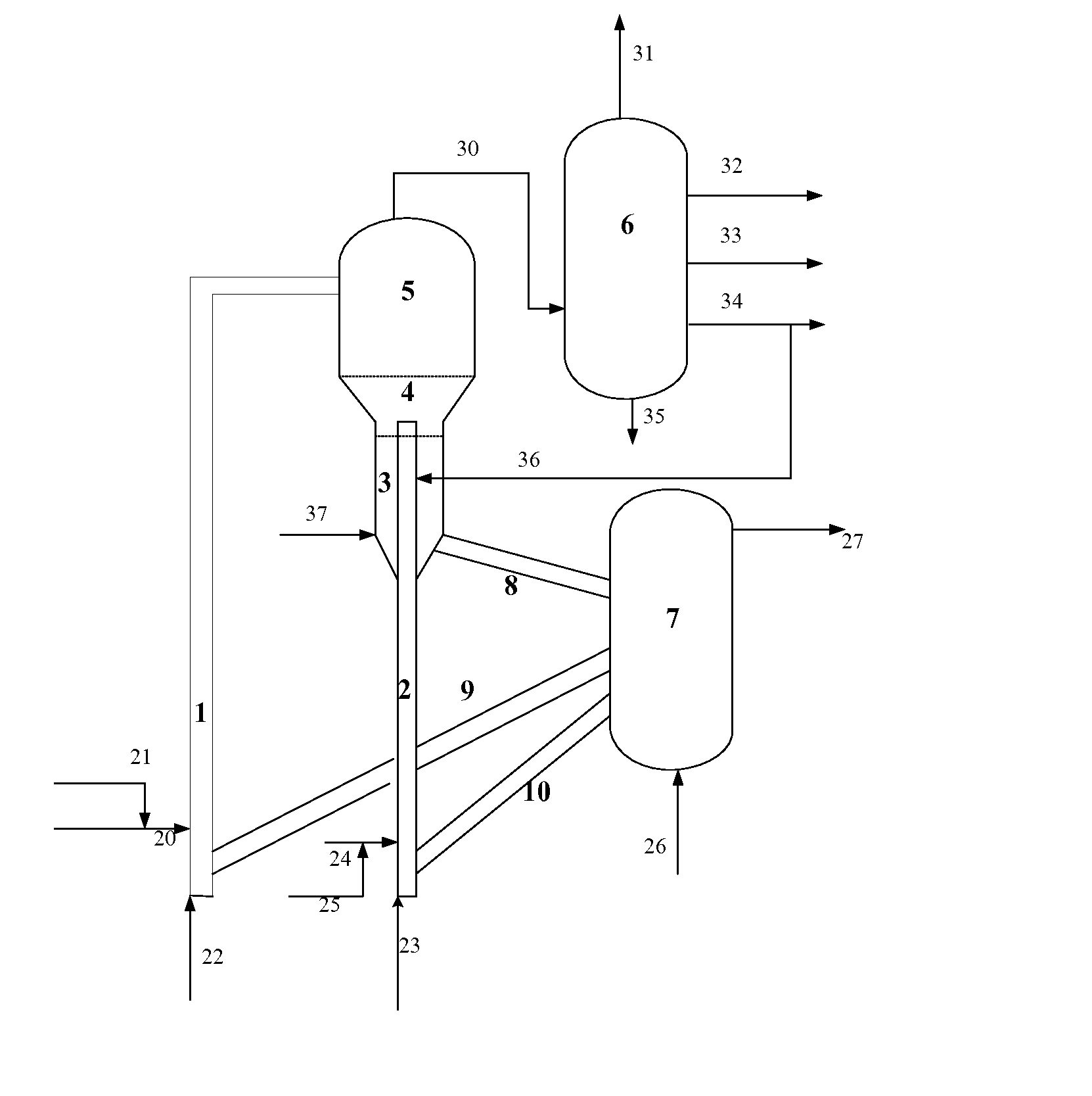
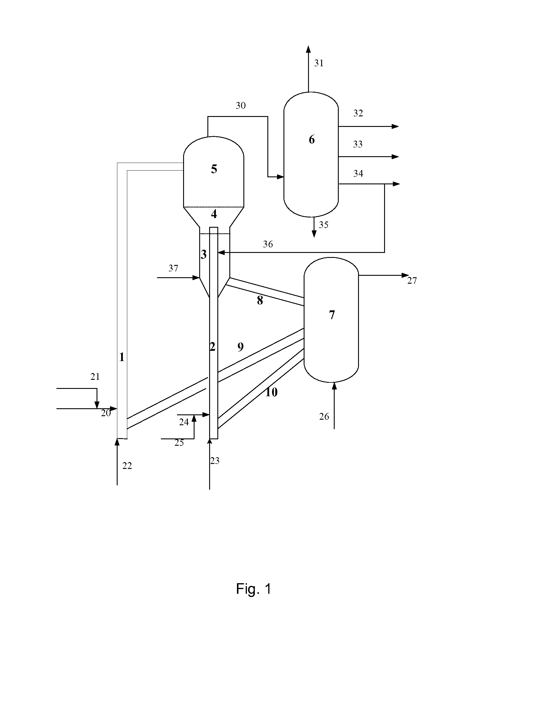
The present invention provides a catalytic cracking apparatus and method for increasing the yield of low olefins (propylene) and the conversion of heavy oil. The method optimizes the process flow and provides a suitable catalyst. Additionally, the invention selectively converts different feedstocks by providing a quick separation device at the end of the first riser reactor. The hydrocarbon product is then injected as feedstock into the second riser reactor connected to the fluidized bed reactor, and the apparatus / process-self-produced cracked heavy oil is introduced into the second riser reactor and / or the fluidized bed reactor to take part in the conversion reaction. This increases the heavy oil conversion depth for the whole apparatus / process and increases the propylene yield. The method also decreases the hydrocarbon product partial pressure and shortens the residence time in the disengager, resulting in increased propylene production and decreased yields of dry gas and coke.

Problems solved by technology

These processes use a single riser reactor or a combination of a single riser reactor and a dense bed and have problems of high dry gas and coke yields.
Said method has a low propylene yield and a low heavy oil conversion capability.
Said method has a limited effect of decreasing the dry gas yield and increasing the heavy oil conversion capability.

Method used


Image

  • Catalytic cracking apparatus and process
  • Catalytic cracking apparatus and process

Examples


example 1

[0098]This example was carried out in a pilot apparatus. The feedstock is a mixture of the olefin-rich cracked light gasoline C and the cracked heavy oil A (at the ratio of C:A=1:1.5). The catalyst was MMC-2. In the pilot apparatus operating in a continuous reaction-regeneration manner, the inner diameter of the riser reactor was 16 mm, the height of the same was 3200 mm, and the outlet of the riser reactor was connected to the fluidized bed reactor, wherein the inner diameter of the fluidized bed reactor was 64 mm and the height of the same was 600 mm. All the feeds entered the apparatus through the nozzle at the bottom of the riser reactor to participate in the reaction.

[0099]This example was conducted in one-through operation mode without the reprocessing of the cracked heavy oil. A high-temperature regenerated catalyst entered the bottom of the reaction section of the riser reactor via the regenerated catalyst pipeline from the regenerator, and flowed upwards under the action of...

example 2

[0104]This example was carried out in the pilot apparatus as mentioned in Example 1. The olefin-rich cracked light gasoline C and the cracked heavy oil A were injected at a ratio of 1:1, wherein the feedstock C was injected into the riser reactor through the feeding nozzle at the bottom of the riser reactor and the feedstock A was injected into the riser reactor through the feeding nozzle at the half of the riser reactor length to take part in the reaction.

[0105]The major operation conditions and results of this example are listed in Table 4.

example 3

[0106]This example was carried out in the pilot apparatus as mentioned in Example 1. The olefin-rich cracked light gasoline C and the cracked heavy oil A were injected at a ratio of 1:1.2, wherein the feedstock C was injected into the riser reactor through the feeding nozzle at the bottom of the riser reactor and the feedstock A was injected into the riser reactor through the feeding nozzle at the bottom of the fluidized bed to take part in the reaction.

[0107]The major operation conditions and results of this example are listed in Table 4.


PUM


Abstract

The present invention discloses catalytic cracking apparatus and process, which are useful for catalytic cracking of heavy oils with a high heavy oil conversion, a high propylene yield and low dry gas and coke yields.

Description

TECHNICAL FIELD[0001]The present invention relates to a catalytic cracking apparatus and process.BACKGROUND[0002]Heavy oil catalytic cracking is an important process for producing lower olefins such as ethylene, propylene and butylene.[0003]The commercial process of heavy oil catalytic cracking to produce lower olefin includes those disclosed in U.S. Pat. No. 4,980,053, U.S. Pat. No. 5,670,037 and U.S. Pat. No. 6,210,562. These processes use a single riser reactor or a combination of a single riser reactor and a dense bed and have problems of high dry gas and coke yields.[0004]Recently, more and more attentions are paid to the technology of using two risers to produce propylene.[0005]CN101074392A discloses a method for producing propylene and gasoline diesel-oil by two-section catalyzed cracking style, which is carried out by adopting two-section lift pipe catalyzing process and catalyst with molecular sieve, taking heavy petroleum hydrocarbon or various animal and vegetable oils co...

Claims


Application Information

Patent Timeline
IPC IPC(8): C07C1/20B01J8/24
CPCC10G51/026C10G51/06C10G2300/4018C10G2300/1014C10G2300/1018C10G2400/20C10G2300/301C10G2300/4093C10G2300/708C10G11/18C10G11/20C10G2300/104C10G51/00C10G2400/02
Inventor XIE, CHAOGANGGAO, YONGCANLU, WEIMINLONG, JUNCUI, YANZHANG, JIUSHUNYANG, YINANMA, JIANGUOLI, ZHENGJIANG, NAN
Owner CHINA PETROCHEMICAL CORP
Learn More