System and method to flag a source of data corruption in a storage subsystem using persistent source identifier bits

a technology of persistent source and storage subsystem, which is applied in the field of storage devices, can solve the problems of data corruption, high risk, and high priority of data corruption

Active Publication Date: 2013-01-03
AVAGO TECH INT SALES PTE LTD
View PDF3 Cites 16 Cited by
  • Summary
  • Abstract
  • Description
  • Claims
  • Application Information

AI Technical Summary

Benefits of technology

[0007]The objects, features and advantages of the present invention include providing a detection system in a data storage environment that may (i) provide a boundary and/or structural check technique to verify whether protocol delivered data has been corrupted while the data is held in a host interface buffer of a target controller, (ii) provide asynchronous notification to the host layer if the data held in the buffers is compromised, (iii) provide unique stage wise Cyclic Redundancy Check (CRC) based checksum wrapped to the transaction data as the data navigates through one or more entities behind the array controller, (iv) provide progressive CRC checksum mechanism where the CRC of the predecessor entity is decoded and/or checked by a successive entity and/or is replaced with a present entity specific CRC, (v) provide Source Identifier (SID) fields defined to flag the source of data corruption during the process of data commit to one or more disks, (vi) provide a persistent index table containing SID fields in a non-volatile storage for subsequent field analysis, (vii) provide a bit identifier within an SID field to detect the flow integrity of the I/O transaction, (viii) provide an option to perform a quick scrub of a persistent SID field to identi

Problems solved by technology

Data corruption occurs when data stored on a block of data on a disk is incorrect.
Data corruption is a high risk and very high priority issue for any customer.
Management of data corruption is a critical issue.
Data corruption can include bit corruption (bit flip while data at store or in-flight), lost writes,

Method used


Image

  • System and method to flag a source of data corruption in a storage subsystem using persistent source identifier bits
  • System and method to flag a source of data corruption in a storage subsystem using persistent source identifier bits
  • System and method to flag a source of data corruption in a storage subsystem using persistent source identifier bits

Examples


Embodiment Construction

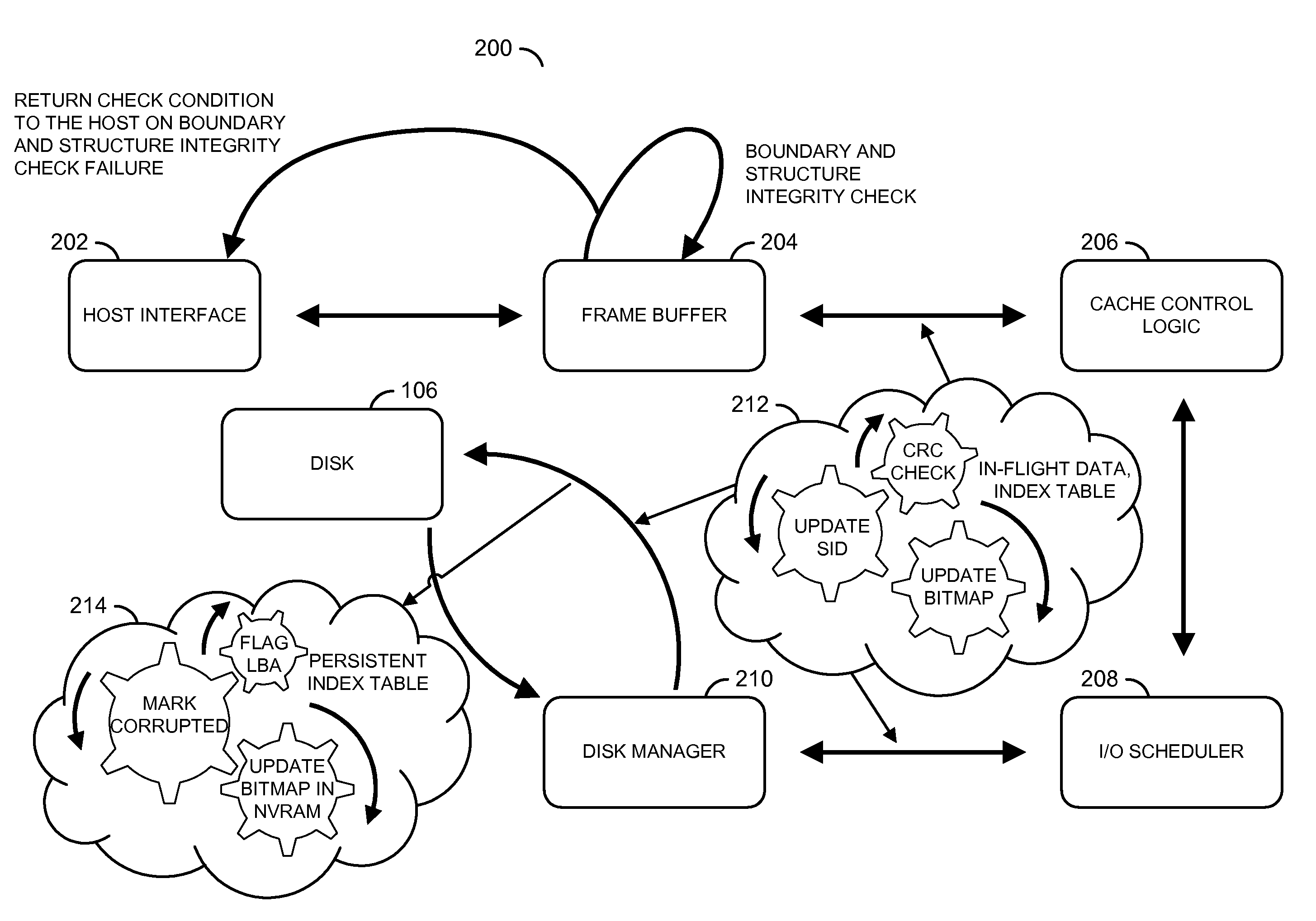
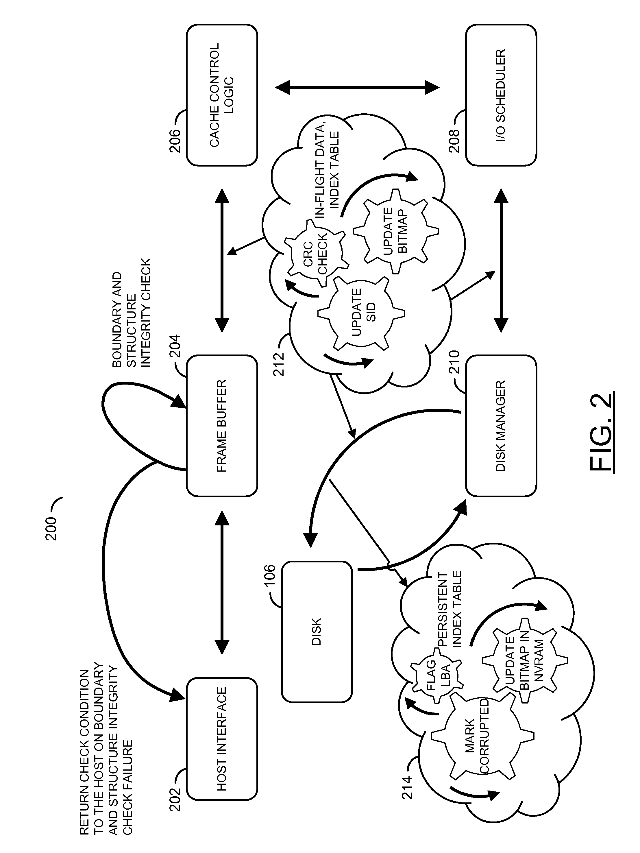
[0012]The present invention may provide a system and / or method to detect in-flight data corruption. The system may flag the source as data from a host traverses within an array controller through one or more hierarchical entities enroute to a disk. The source of data corruption may be flagged using bit field stored in an index table. A boundary marker and / or asynchronous notification may be defined where a data scrub may be performed in addition to other protocol defined data integrity techniques. A faster and multi-level data scrub of data during a store operation may be defined and / or assisted by a persisted bit field. The system may provide an isolation mechanism between different classes of data corruption (e.g., between in-flight and / or in-store data corruption, etc.).

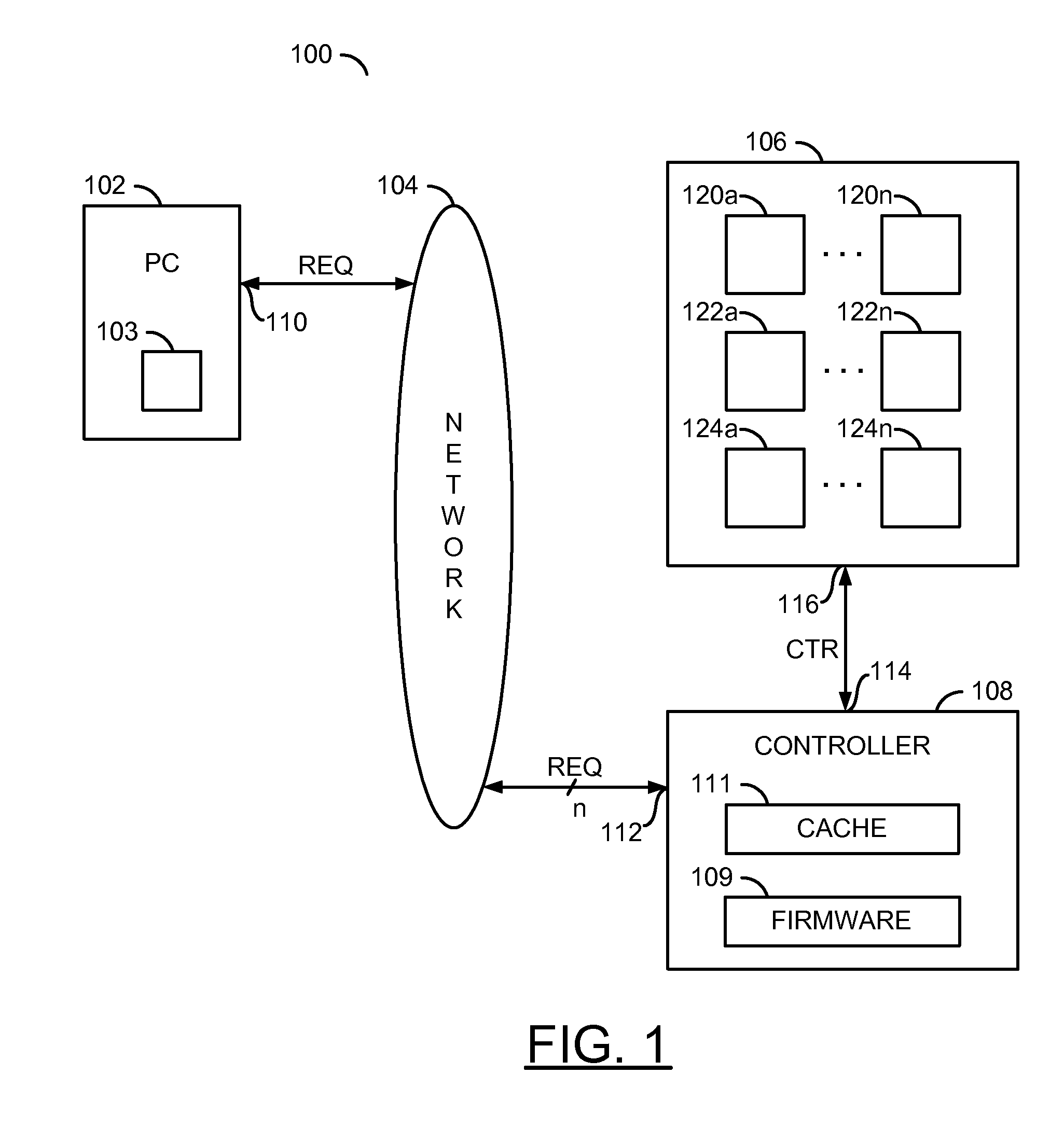
[0013]Referring to FIG. 1, a block diagram of a system 100 is shown illustrating a context of the present invention. The system 100 generally comprises a block (or circuit) 102, a network 104, a block (or circuit)...


PUM


Abstract

An apparatus comprising an array controller and a frame buffer. The array controller may be configured to read/write data to/from a drive array in response to one or more input/output requests. The frame buffer may be implemented within the array controller and may be configured to perform (i) a first data integrity check to determine a first type of data error and (ii) a second data integrity check to determine a second type of data error. The frame buffer may log occurrences of the first type of error and the second type of error in a field transmitted with the data. The field may be used to determine a source of possible corruption of the data.

Description

FIELD OF THE INVENTION[0001]The present invention relates to storage devices generally and, more particularly, to a method and / or apparatus to flag a source of data corruption in a storage subsystem using persistent source identifier bits.BACKGROUND OF THE INVENTION[0002]Data corruption occurs when data stored on a block of data on a disk is incorrect. Data corruption is a high risk and very high priority issue for any customer. Management of data corruption is a critical issue. Data corruption can include bit corruption (bit flip while data at store or in-flight), lost writes, misdirected writes, and torn / truncated writes. There are many conventional approaches to detection of data corruption depending on the layer where the data is managed.[0003]A conventional host application layer has built-in mechanisms to detect data corruption or data integrity errors using multiple approaches (i.e., a data integrity field (DIF)). The interface protocol also defines multiple approaches to pre...

Claims


Application Information

Patent Timeline
IPC IPC(8): G06F11/07
CPCG06F2211/1088G06F11/1004G06F11/0772G06F11/0727
Inventor JIBBE, MAHMOUD K.RAGENDRAN, ARUNKUMARROSSARIO, BRITTOKANNAN, SENTHILPANDURANGAN, PADMANABHAN
Owner AVAGO TECH INT SALES PTE LTD
Why Eureka
Try Eureka