Wireless energy transfer for person worn peripherals

a peripheral and wireless technology, applied in the direction of transformers, inductances, protective garments, etc., can solve the problems of increased burden of carrying, operating and maintaining multiple batteries, fuel cells, and the like, and user's carrying energy is underutilized, and may be carrying too much battery or stored energy capacity,

Inactive Publication Date: 2013-01-10
WITRICITY CORP
View PDF20 Cites 273 Cited by
  • Summary
  • Abstract
  • Description
  • Claims
  • Application Information

AI Technical Summary

Benefits of technology

[0011]Wireless energy transfer can enable such peripheral devices to be powered from a wearable battery pack or portable power generator, without the safety and ergonomic drawbacks of multiple wired connections that tether the mobile electronic devices, such as a head worn device or helmet to the user.

Problems solved by technology

As advanced mobile communication, computing, and sensing devices become more essential, the burden of carrying, operating, and maintaining multiple batteries, fuel cells, and the like, increases.
Large numbers of devices may mean a large number of batteries that may require management and / or monitoring by the user.
In systems where each device has its own energy source, i.e. batteries, the stored energy may be underutilized and may lead to significant or unnecessary extra weight that may need to be carried by the user.
As a result in many use scenarios, the user will be underutilizing the carried energy and perhaps carrying too much battery or stored energy capacity.
The underutilization of carried energy may be problematic for weight sensitive devices and applications.
Underutilization of energy for a device attached to a helmet, for example, may mean a significant weight penalty that a user has to tolerate on their head.
However, such devices may be tethered to the person's battery pack with cables.
For devices such as headlamp, microphones, night vision goggles, and the like, that are carried on a person's head or helmet, the cables may be uncomfortable, limit movement, pose a safety risk (since cables may get snagged or caught on objects and obstacles), and reduce the reliability of the system.

Method used


Image

  • Wireless energy transfer for person worn peripherals
  • Wireless energy transfer for person worn peripherals
  • Wireless energy transfer for person worn peripherals

Examples


Embodiment Construction

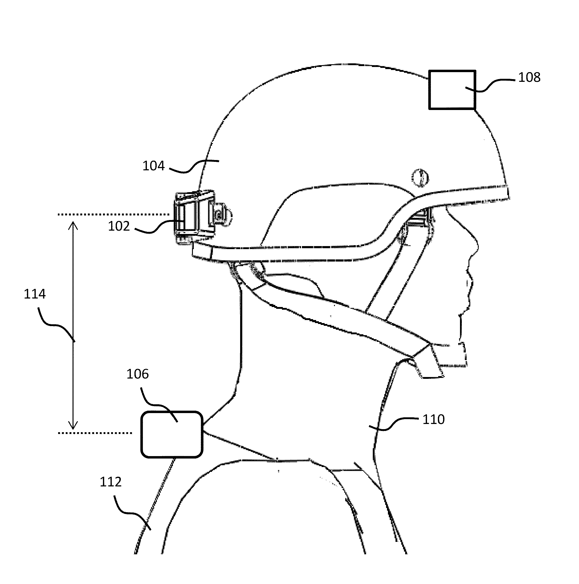
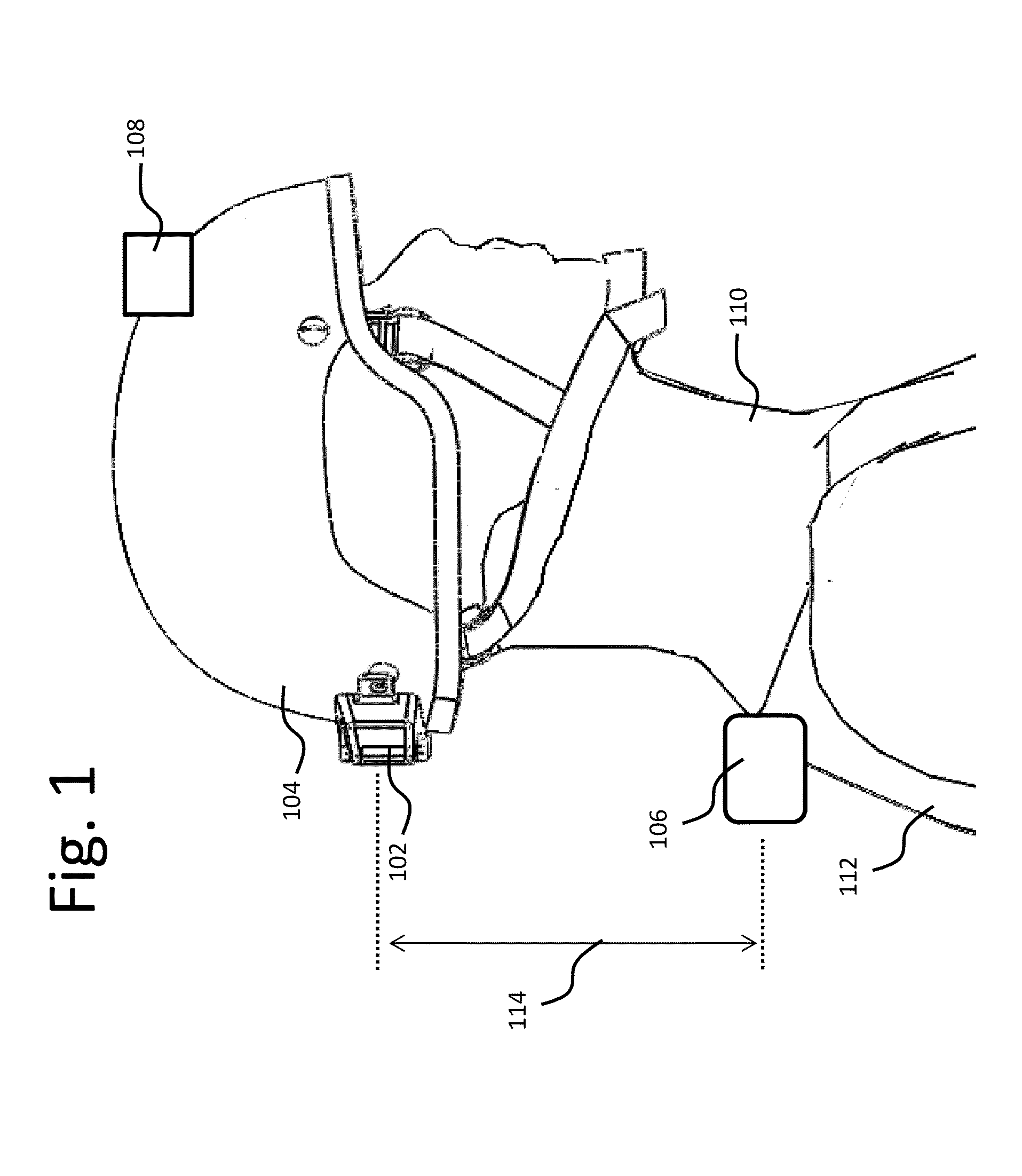
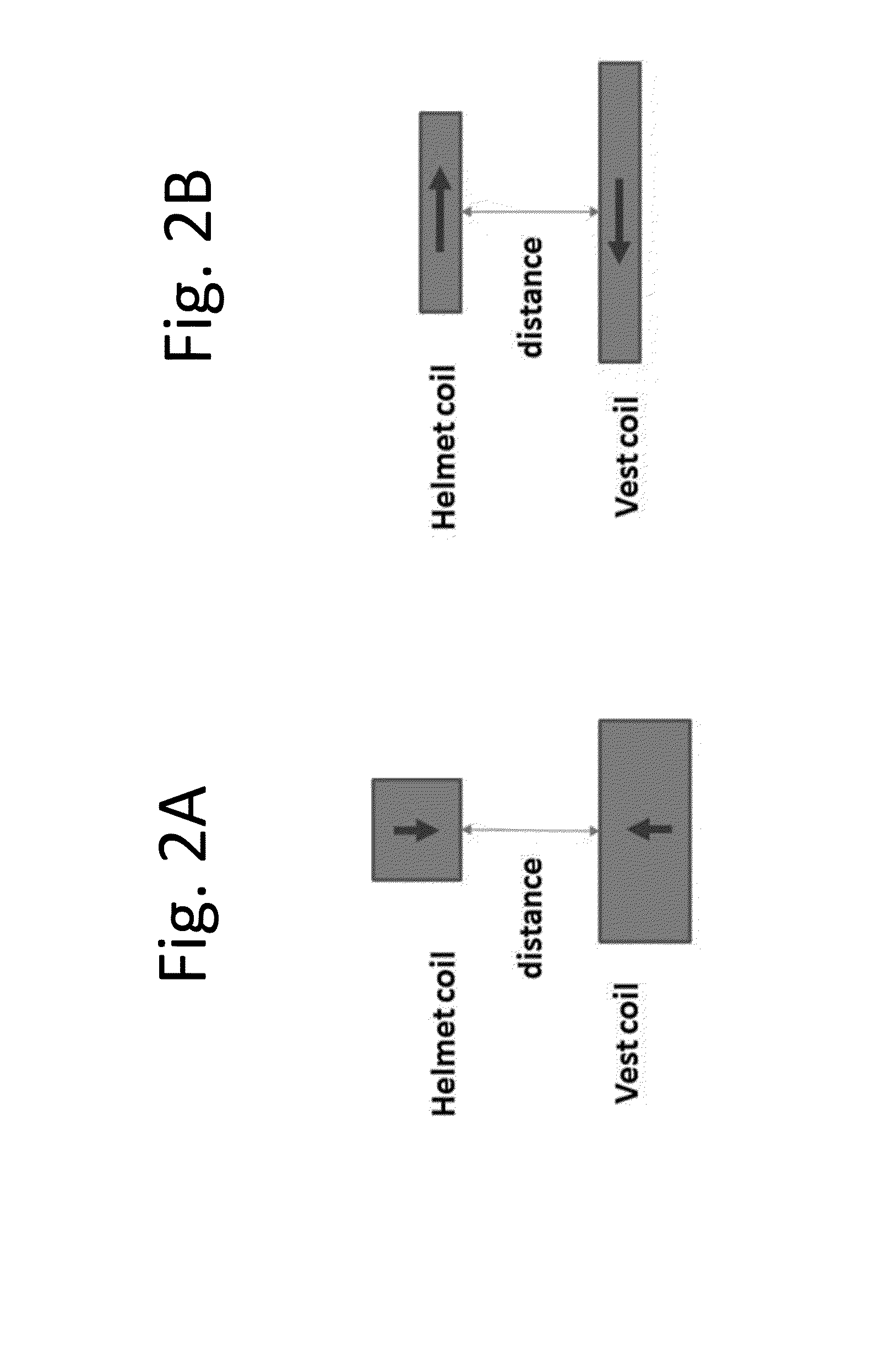
[0023]A wireless energy transfer system may be used to wirelessly transfer energy from one or more central batteries and / or fuel cells and / or solar panels and / or other types of energy packs worn on a vest, backpack, harness, shirt, pant, belt, coat, or any type of clothing and the like, to a head worn or helmet mounted electric or electronic device. The wireless energy transfer system may use strongly-coupled magnetic resonators. The resonators may have a high quality factor Q>100. The two resonators exchanging energy by have sqrt(Q1Q2)>100. The system comprises at least one wireless energy source resonator, which might be embedded or attached to the user's equipment, clothing, vest, backpack and the like. The source resonator generates an oscillating magnetic field which may be received by one or more energy capture device resonators which may be integrated with the helmet or device. In embodiments 5 watts or more of power may be transferred across a gap of 10 cm or 18 cm or more f...


PUM


Abstract

Described is a system for wireless energy transfer for person worn peripherals. The system makes use of a technique referred to as strongly-coupled magnetic resonance to transfer energy across a distance without wires and enables efficient transfer of energy over distances of 10 to 18 cm or more. The system comprises a resonant power source, which could be embedded in a person's equipment vest or backpack receiving power from a central battery pack or micro fuel cell, and a resonant power capture unit which could be integrated with the helmet or hand held weapon, electronic device, and the like that may be carried or handled by a person.

Description

CROSS-REFERENCE TO RELATED APPLICATIONS[0001]This application claims the benefit of U.S. provisional patent application 61 / 505,593 filed Jul. 8, 2011.BACKGROUND[0002]1. Field:[0003]This disclosure relates to wireless energy transfer to person worn peripherals and apparatus to accomplish such transfer.[0004]2. Description of the Related Art[0005]Energy or power may be transferred wirelessly using a variety of known radiative, or far-field, and non-radiative, or near-field, techniques as detailed, for example, in commonly owned U.S. patent application Ser. No. 12 / 613,686 published on May 6, 2010 as US 2010 / 010909445 and entitled “Wireless Energy Transfer Systems,” U.S. patent application Ser. No. 12 / 860,375 published on Dec. 9, 2010 as 2010 / 0308939 and entitled “Integrated Resonator-Shield Structures,” U.S. patent application Ser. No. 13 / 222,915 published on Mar. 15, 2012 as 2012 / 0062345 and entitled “Low Resistance Electrical Conductor,” U.S. patent application Ser. No. 13 / 283,811 pu...

Claims


Application Information

Patent Timeline
Patent Type & Authority Applications(United States)
IPC IPC(8): A42B3/04H02J17/00A41D1/04
CPCA42B3/0406H02J17/00H02J7/025H02J50/12H02J50/70H02J7/342H02J50/50
Inventor KURS, ANDRE B.KESLER, MORRIS P.HALL, KATHERINE L.VERGHESE, SIMON
Owner WITRICITY CORP
Why Eureka
Try Eureka