
Radiant Superheater

a superheater and radiant technology, applied in the field of radiant superheaters, can solve the problems of reducing the thermal efficiency of the boiler, affecting the durability of the radiant superheater, and affecting the performance of the boiler

Inactive Publication Date: 2013-01-10
FOSTER WHEELER NORTH AMERICA CORP
View PDF7 Cites 4 Cited by
  • Summary
  • Abstract
  • Description
  • Claims
  • Application Information

AI Technical Summary

Benefits of technology

The patent describes a method of using a radiant superheater (RSH) to improve the efficiency of a boiler. The RSH consists of several parallel elements, each with a series of passes. The steam flows through the RSH and its temperature increases as it passes through the elements. This design helps to reduce metal temperatures and allows for the use of thinner minimum wall thickness in the RSH. Additionally, a single superheater can be used in the boiler to achieve better efficiency, or multiple superheaters can be connected in series to increase duty. Overall, this method improves the efficiency of the boiler and reduces costs associated with the superheater.

Problems solved by technology

Due to high flame temperature in the furnace, the durability of radiant superheaters may suffer from overheating.
The above-mentioned prior art solutions may adversely alter the heat duty among the superheating stages, and thus, lower the thermal efficiency of the boiler, or they address primarily convective dominant heat transfer.

Method used


Image

  • Radiant Superheater
  • Radiant Superheater
  • Radiant Superheater

Examples


Embodiment Construction

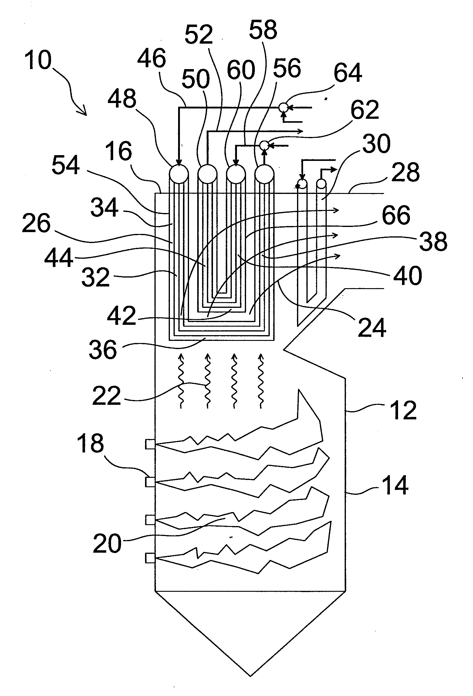
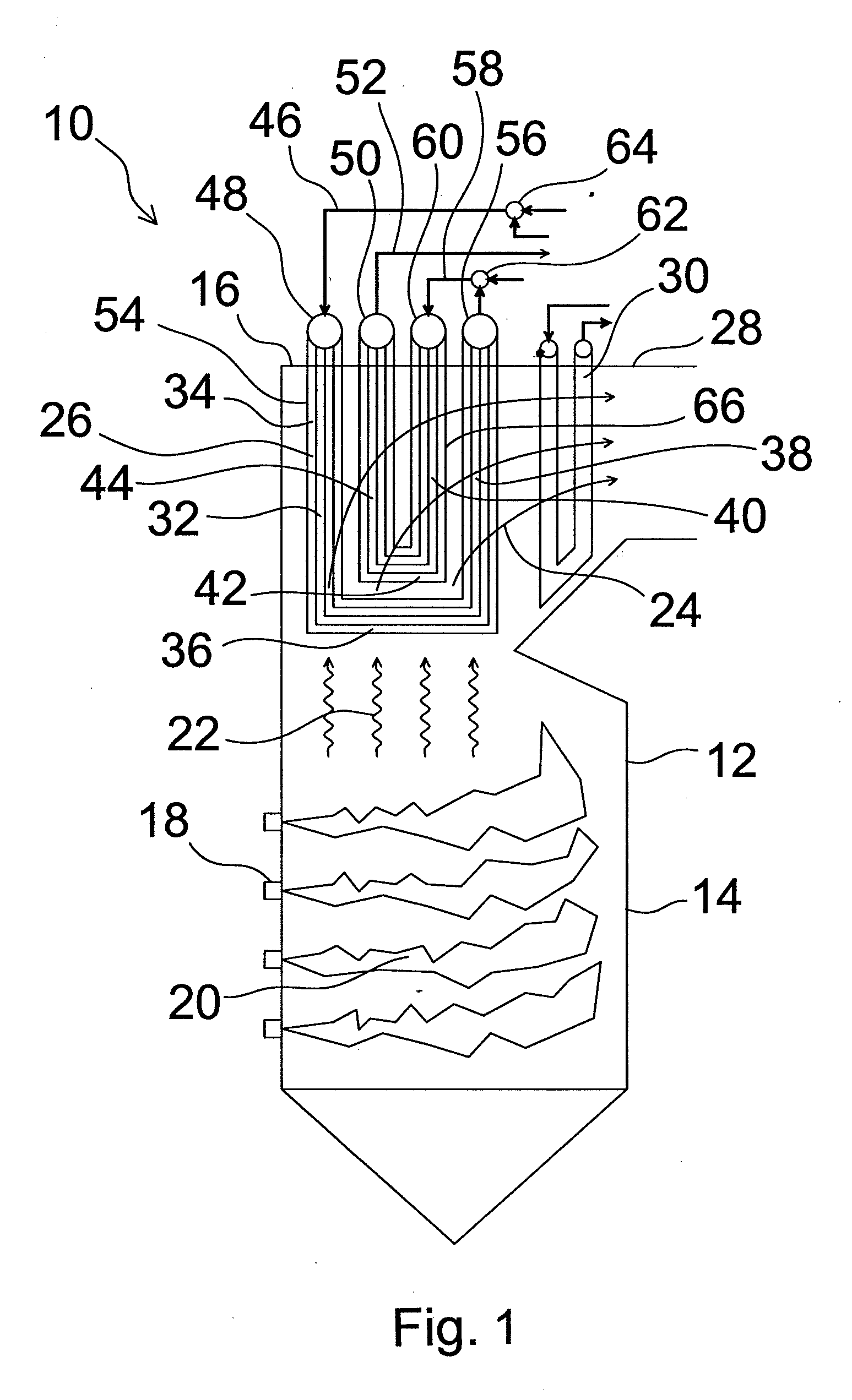
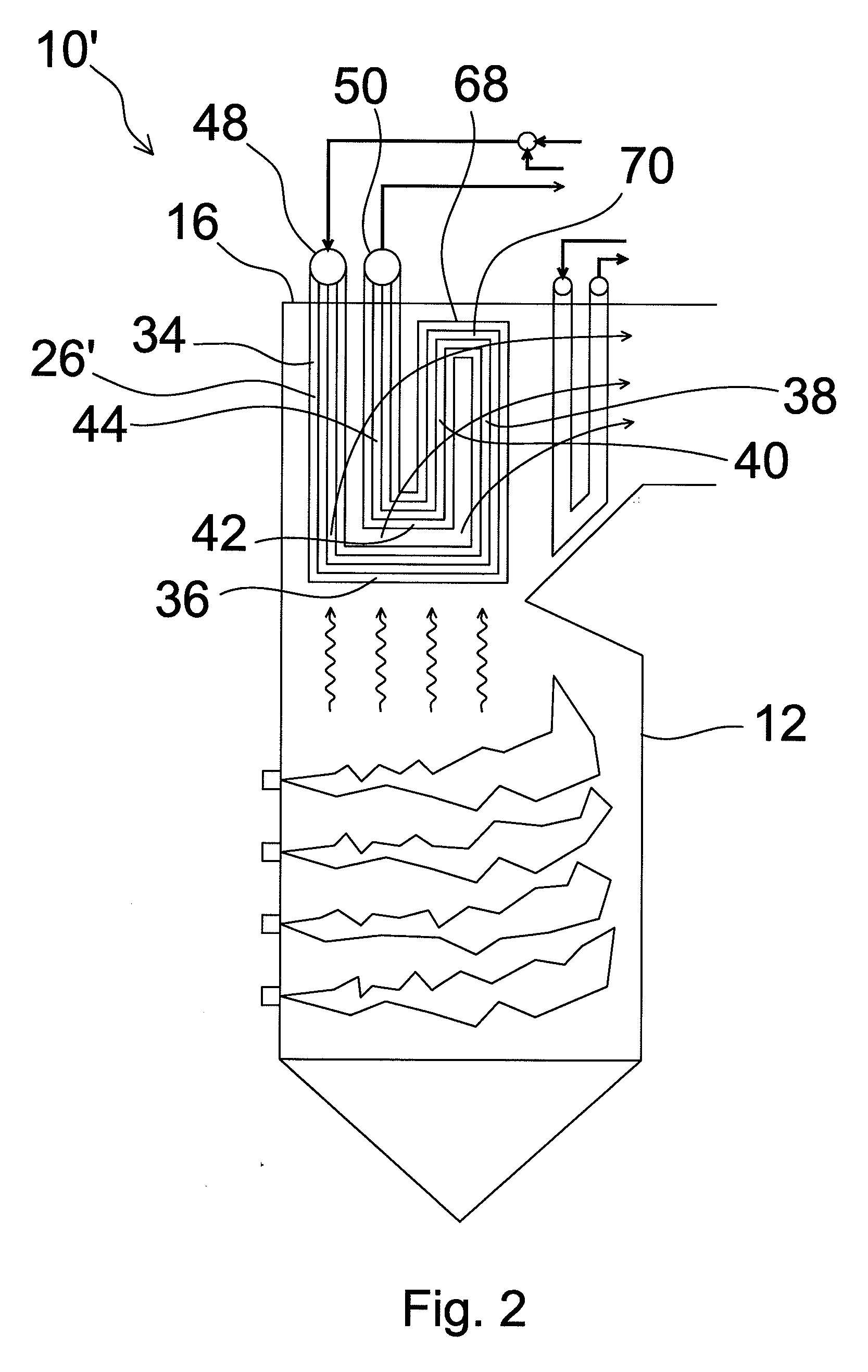
[0024]FIG. 1 schematically shows a pulverized coal firing supercritical or ultrasupercritical boiler 10 in accordance with a first embodiment of the present invention. The boiler comprises a furnace 12 with water-cooled enclosure walls 14 and a roof 16. At the boiler walls 14 are arranged burners 18 for firing pulverized coal and producing a flame zone 20 into the furnace 12. From the flame zone 20 is conducted heat by radiation 22 and by hot flue gases 24. Because the radiation heat depends on the fourth power of the absolute temperature, heat conduction by radiation dominates in regions having direct visibility to the high temperature flame zone 20. The upper portion of the furnace 12 comprises a hanging radiant superheater 26, in which steam is superheated, to be finally conducted to a steam turbine (not shown) to generate power. Horizontal pass 28 immediately downstream of the furnace 12 comprises further hanging superheaters, such as finishing superheaters 30.

[0025]The radiant ...


PUM


Abstract

A radiant superheater arranged to hang at the upper portion of a furnace of a boiler. The radiant superheater is substantially planar and includes a first vertical pass, a first connection pass, a second vertical pass, a third vertical pass, a second connection pass, and a fourth vertical pass. Each vertical pass includes an upper end and a lower end. The vertical passes are connected in series, so that steam to be superheated enters at the upper end of the first vertical pass and flows through the first vertical pass and from the lower end of the first vertical pass via the first connection pass to the lower end of the second vertical pass and through the second vertical pass and from the upper end of the second vertical pass to the upper end of the third vertical pass and through the third vertical pass and from the lower end of the third vertical pass via the second connection pass to the lower end of the fourth vertical pass and through the fourth vertical pass, to be discharged from the upper end of the fourth vertical pass. The first connection pass is arranged below the second connection pass so as to shield the second connection pass from radiation from the lower portion of the furnace.

Description

BACKGROUND OF THE INVENTION[0001]1. Field of the Invention[0002]The present invention relates to a radiant superheater. More particularly, the present invention relates to a radiant superheater arranged to hang at the upper portion of a furnace of a boiler, especially, of a supercritical or ultra supercritical pulverized coal firing boiler.[0003]2. Description of the Related Art[0004]In practice, all power boilers of today have superheaters (SH), i.e., heat exchangers, in which the temperature of high pressure steam produced in an evaporator is raised above the saturation temperature. Superheated steam is then conducted to a high pressure steam turbine to produce steam power. Many boilers also comprise a reheater, in which the temperature of lower pressure steam released from the high pressure steam turbine is raised again, in order to produce more power by an intermediate pressure steam turbine. In the following, the term “superheater” may refer to either an actual superheater or a...

Claims


Application Information

Patent Timeline
Patent Type & Authority Applications(United States)
IPC IPC(8): F22G1/06F22G7/08
CPCF22G1/08F22G1/06
Inventor SELTZER, ANDREW H.FAN, ZHENHACK, HORSTGAGLIANO, MICHAELSTANKO, GREGORY J.
Owner FOSTER WHEELER NORTH AMERICA CORP
Learn More