Shielding for cable components

a technology for shielding and cable components, applied in the direction of insulated conductors, power cables, cables, etc., can solve the problems of degrading the electrical performance of the cable, limited use of conductive materials in this arrangement, and formation of shielding of such materials

Inactive Publication Date: 2013-01-10
GENERAL CABLE TECH CORP
View PDF8 Cites 32 Cited by
  • Summary
  • Abstract
  • Description
  • Claims
  • Application Information

AI Technical Summary

Problems solved by technology

Crosstalk or interference often occurs because of electromagnetic coupling between the twisted pairs within the cable or other components in the cable, thereby degrading the cable's electrical performance.
The substrate being provided for durability as the foil itself is not suitable for processing in a manufacturing environment.
The conductive materials that can be used in this arrangement, however, are limited to those specific conductive foils that can be processed into a foil sheet.
Shielding formed of such materials, however, is not advantageous in high performance communication cables, because the materials tend to attenuate the signal causing excessive power loss.
In UTP cables, the increased NEXT (near end crosstalk) performance required by 10 gigabit Ethernet applications necessitates the use of very large fillers, which in

Method used


Image

  • Shielding for cable components
  • Shielding for cable components
  • Shielding for cable components

Examples


Embodiment Construction

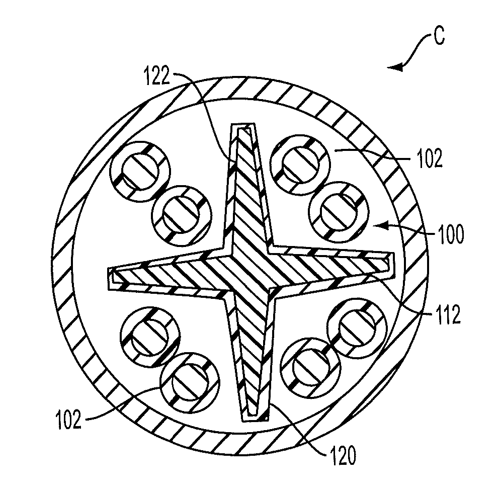
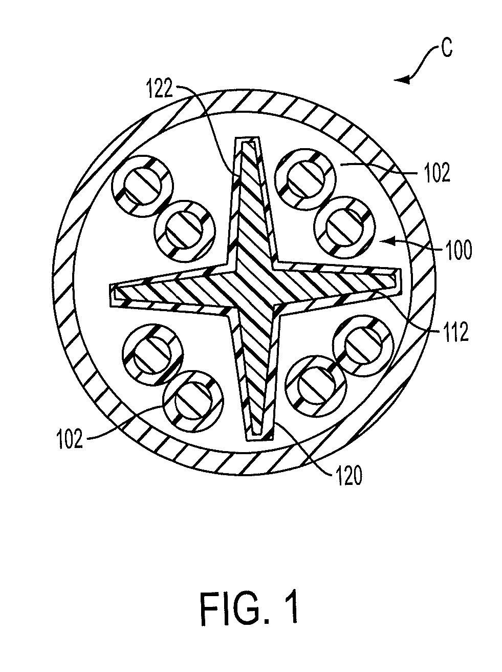
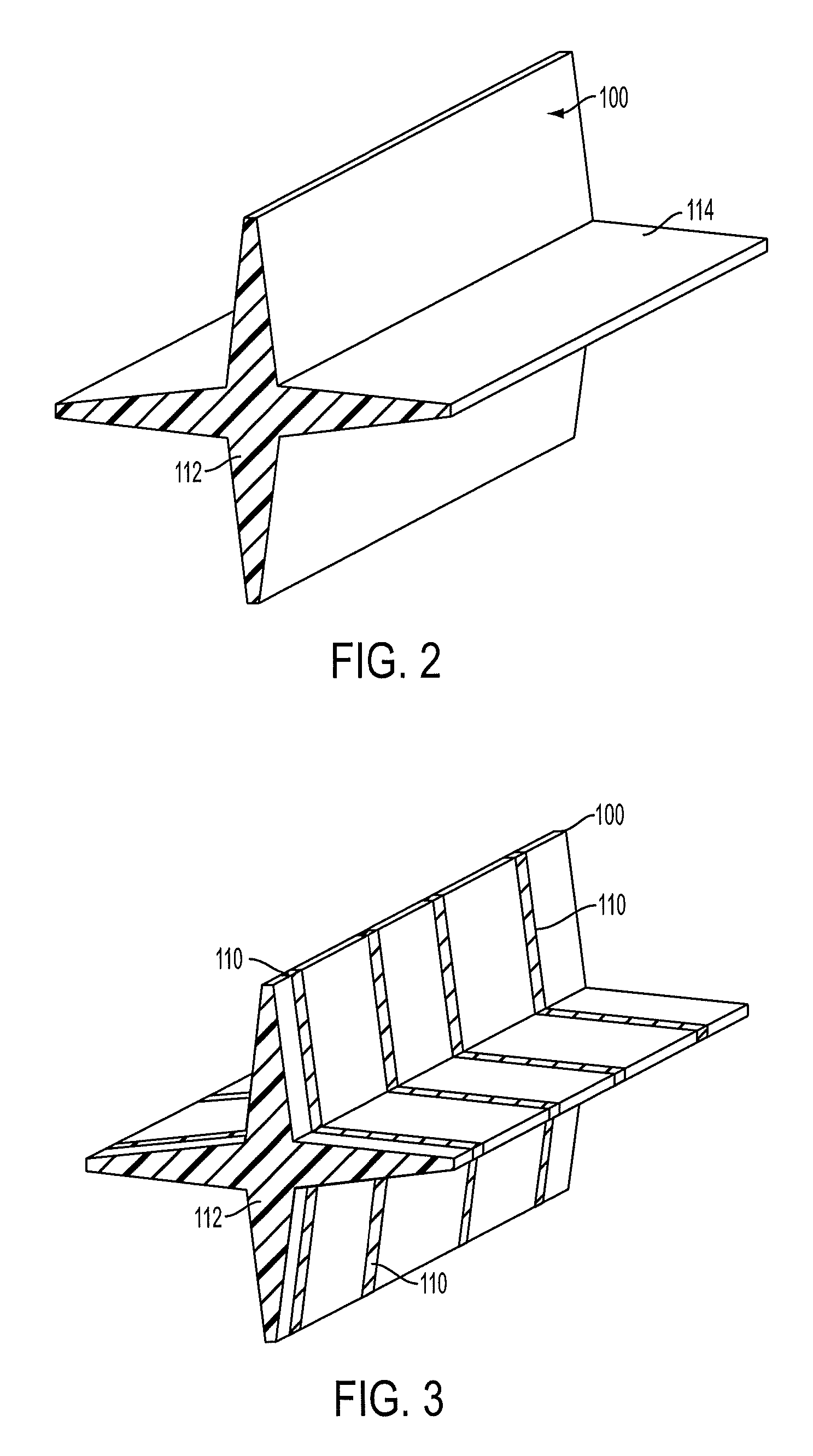
[0025]Referring to FIGS. 1-9, a cable component 100 of a cable C includes a shielding 120 according to an exemplary embodiment of the present invention. The cable component 100 may be a separator, for example, that isolates one or more pairs of insulated wires 102 in the core of the cable C. The separator may be a cross-web (FIG. 1) or a tube (FIG. 8), for example. By using shielding 120 with the component 100, the size of the component 100 may be reduced, thereby reducing the overall radial size of the cable C, and the flexibility of the cable C is increased. Moreover, the need for a shielding layer wrapped around the core of the cable is eliminated. The shielding 120 is also easily applied to the component 100 and improves both electrical and flame / smoke performance. The shielding 120 is preferably discontinuous to eliminate the need for grounding.

[0026]A method according to an exemplary embodiment of the present invention generally includes the steps of applying a coated shieldin...


PUM


Abstract

A shielded cable component and method that comprises a human body that has an outer surface and the main body is formed of a dielectric material and a coating that is applied to the outer surface of the main body where the coating includes a conductive or semi-conductive shielding material. An outer layer is disposed on the coating that completely encapsulates the coating and the main body and the outer layer is formed of a dielectric material.

Description

RELATED APPLICATION[0001]This application claims the benefit of U.S. Provisional Application No. 61 / 505,772, filed Jul. 8, 2011 and entitled Shielding for Cable Components, and U.S. provisional application No. 61 / 513,220, filed Jul. 29, 2011, and entitled Method For Shielding A Substrate.FIELD OF THE INVENTION[0002]The present invention provides a shielding for cable components that uses a conductive or semi-conductive coating to reduce or eliminate internal and external cable crosstalk as well as other EMI / RF from sources outside of the cable. The present invention also relates to a method for applying the shielding to a substrate, such as a cable component.BACKGROUND OF THE INVENTION[0003]A conventional communication cable typically includes a number of insulated conductors that are twisted together in pairs and surrounded by an outer jacket. Crosstalk or interference often occurs because of electromagnetic coupling between the twisted pairs within the cable or other components in...

Claims


Application Information

Patent Timeline
IPC IPC(8): H01B9/02
CPCH01B13/0026H01B11/08B82Y30/00Y10S977/734H01B11/06H01B13/22
Inventor WEITZEL, JARED D.CAMP, II, DAVID P.
Owner GENERAL CABLE TECH CORP
Why Eureka
Try Eureka