Measurement apparatus, measurement method, and feature identification apparatus

a technology of measurement equipment and feature identification, which is applied in the direction of instruments, navigation instruments, image enhancement, etc., can solve the problems of huge cost and time to sophisticate and improve the precision of road management ledgers across the country

Active Publication Date: 2013-01-10
MITSUBISHI ELECTRIC CORP +1
View PDF3 Cites 10 Cited by
  • Summary
  • Abstract
  • Description
  • Claims
  • Application Information

AI Technical Summary

Benefits of technology

[0017]Further, the present invention aims to aid the user to specify a feature for the measurement target in order to provide measured result of the point desired by the user.

Problems solved by technology

Therefore, it requires huge cost and time to sophisticate and improve the precision of the road management ledgers across the country.

Method used


Image

  • Measurement apparatus, measurement method, and feature identification apparatus
  • Measurement apparatus, measurement method, and feature identification apparatus
  • Measurement apparatus, measurement method, and feature identification apparatus

Examples


embodiment 1

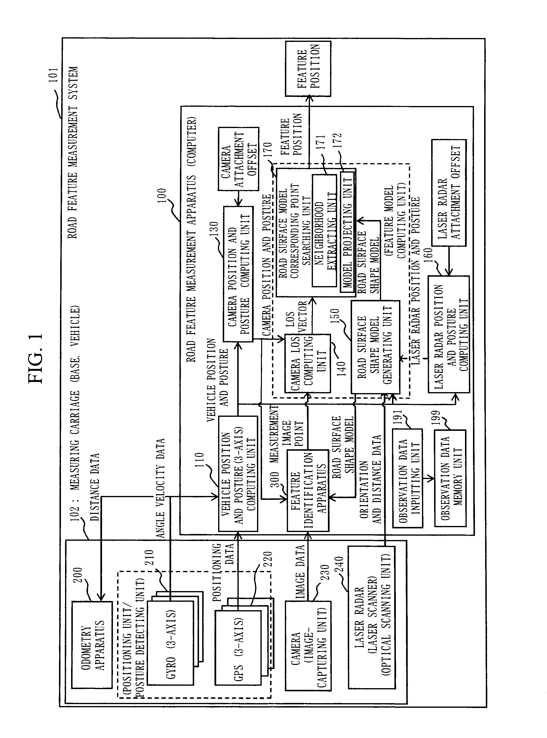
[0061]FIG. 1 shows a system configuration of a road feature measurement system 101 and a functional configuration of a road feature measurement apparatus 100 according to the first embodiment.

[0062]The road feature measurement system 101 in the first embodiment includes an odometry apparatus 200, three gyros 210 (a part of a positioning unit, a posture detecting unit, and a GPS gyro), three GPSs 220 (a part of the positioning unit, the posture detecting unit, and the GPS gyro), a camera 230 (an imaging unit), a laser radar 240 (an optical scanning unit, a laser scanner, and a LRF [Laser Range Finder]), and a road feature measurement apparatus 100 (a computer).

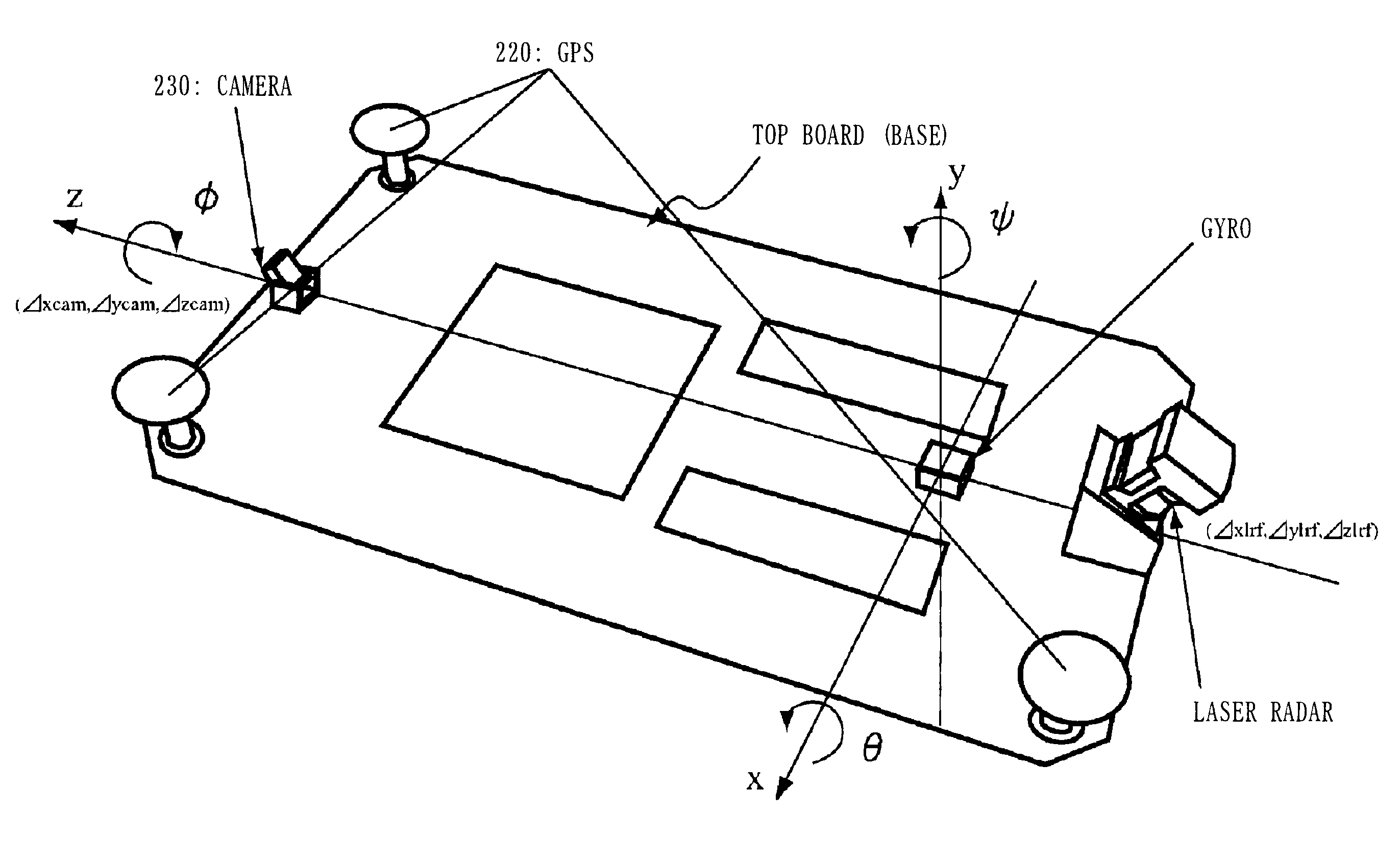
[0063]The odometry apparatus 200, the three gyros 210, the three GPSs 220, the camera 230, and the laser radar 240 (examples of a measurement sensor, respectively) are mounted on a top board 103 (base) (refer to FIG. 4) of a measuring carriage 102 (a vehicle, hereinafter). Here, a positive direction of the Z axis of FIG. 5 corr...

embodiment 2

[0316]In the second embodiment, a road feature measurement screen 400, which is displayed by the image displaying unit 341 in the image displaying process (S204a) of the road feature position measuring process that has been explained in the first embodiment, will be explained.

[0317]FIG. 28 shows a system configuration of a road feature measurement system 101 and a functional configuration of a road feature measurement apparatus B 500 according to the second embodiment.

[0318]The road feature measurement apparatus B 500 corresponds to the road feature measurement apparatus 100 that has been explained in the first embodiment, from which the vehicle position and posture (3-axis) computing unit 110, the road surface shape model generating unit 150, the laser radar position and posture computing unit 160, and a part of the feature identification apparatus 300 (the motion stereo unit 310, the moving body removing unit 320, and the feature identifying unit 330) are removed to the outside.

[0...

embodiment 3

[0362]In the third embodiment, a feature position locating process (S106) performed by the road surface model corresponding point searching unit 170 will be explained.

[0363]Items being different from the first embodiment will be mainly discussed in the following, and items for which explanation is omitted can be considered as the same as the first embodiment.

[0364]FIG. 30 shows a functional configuration of the road surface model corresponding point searching unit 170 according to the third embodiment.

[0365]As shown in FIG. 30, the road surface model corresponding point searching unit 170 includes a neighborhood extracting unit 171, a model projecting unit 172, a neighboring plane calculating unit 173, and a feature position calculating unit 174.

[0366]The model projecting unit 172 projects the point cloud of the road surface shape model on the image plane as explained in the first embodiment.

[0367]The neighborhood extracting unit 171 extracts one neighboring point of the measurement...


PUM


Abstract

It is an object to measure a position of a feature around a road. An image memory unit stores images in which neighborhood of the road is captured. Further, a three-dimensional point cloud model memory unit 709 stores a point cloud showing three-dimensional coordinates obtained by laser measurement which is carried out simultaneously to the image-capturing of the images as a road surface shape model. Using an image point inputting unit 342, a pixel on a feature of a measurement target is specified by a user as a measurement image point. A neighborhood extracting unit 171 extracts a point which is located adjacent to the measurement image point and superimposed on the feature for the measurement target from the point cloud. A feature position calculating unit 174 outputs three-dimensional coordinates shown by the extracted point as three-dimensional coordinates of the feature for the measurement target.

Description

CROSS-REFERENCE TO RELATED APPLICATIONS[0001]This application is a divisional application of and claims the benefit of priority under 35 U.S.C. §120 for U.S. Ser. No. 12 / 527,478, filed Aug. 17, 2009, pending, which is a National Stage application of PCT / JP2008 / 52509, filed Feb. 15, 2008 and claims benefit of priority under 35 U.S.C. §119 from JP 2007-035918, filed Feb. 16, 2007, the entire contents of each of which are incorporated herein by reference.TECHNICAL FIELD[0002]The present invention relates to, for example, a road feature measurement apparatus for measuring a feature position located on the road / side of the road, a feature identification apparatus, a road feature measuring method, a road feature measuring program, a measurement apparatus, a measuring method, a measuring program, measurement position data, a measurement terminal device, a measurement server device, a plotting apparatus, a plotting method, a plotting program, and plotting data.BACKGROUND ART[0003]Recent yea...

Claims


Application Information

Patent Timeline
Patent Type & Authority Applications(United States)
IPC IPC(8): H04N13/02G01B11/24G01C11/00G01C15/00G01C15/04G01C21/00G06T1/00G06T17/05
CPCG01C21/3602G06T7/0057G06T2207/30252G06T2207/20101G06T2207/20221G06T2207/10028G06T7/521
Inventor TAKIGUCHI, JUNICHIKAJIWARA, NAOYUKISHIMA, YOSHIHIROKUROSAKI, RYUJIROHASHIZUME, TAKUMI
Owner MITSUBISHI ELECTRIC CORP
Why Eureka
Try Eureka