Liquid crystal display apparatus

a technology of liquid crystal display and display device, which is applied in the direction of optics, electrical devices, instruments, etc., can solve the problems of defect exiting the design of fig. 1, and achieve the effects of reducing the brightness of 2d images, reducing the optical path difference of light emitted, and deteriorating display quality

Inactive Publication Date: 2013-01-10
SHENZHEN CHINA STAR OPTOELECTRONICS TECH CO LTD
View PDF5 Cites 2 Cited by
  • Summary
  • Abstract
  • Description
  • Claims
  • Application Information

AI Technical Summary

Benefits of technology

[0018]The conventional LCD has the problem that crosstalk easily appears when viewing the 3D images, thereby deteriorating the display quality, and the brightness of the 2D images is reduced. In comparison with the conventional LCD, the LCD apparatus comprises the light adjustment plate disposed between the TFT-LCD module and the phase retarder, and configured to reduce the optical path difference of the light emitted from the phase retarder, so as to reduce crosstalk when viewing the 3D images, and to mitigate the problem that the brightness of the 2D images is reduced.

Problems solved by technology

However, there is a defect exiting in the design of FIG. 1.

Method used


Image

  • Liquid crystal display apparatus
  • Liquid crystal display apparatus
  • Liquid crystal display apparatus

Examples


Embodiment Construction

[0024]The following embodiments are referring to the accompanying drawings for exemplifying specific implementable embodiments of the present invention. Furthermore, directional terms described by the present invention, such as upper, lower, front, back, left, right, inner, outer, side and etc., are only directions by referring to the accompanying drawings, and thus the used directional terms are used to describe and understand the present invention, but the present invention is not limited thereto.

[0025]In the drawings, structure-like elements are labeled with like reference numerals.

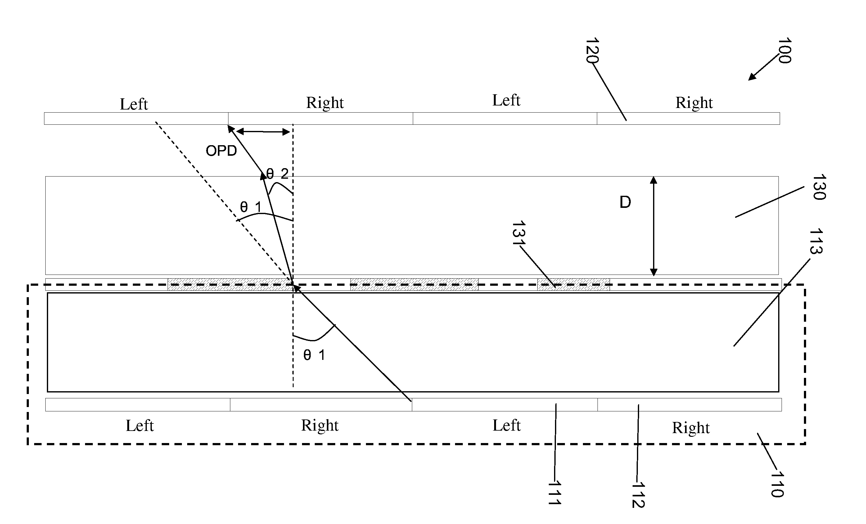
[0026]In a preferred embodiment of the present invention, FIG. 4 is structural diagram showing an LCD apparatus according to the preferred embodiment of the present invention. The LCD apparatus 100 comprises a TFT-LCD module 110 and a corresponding phase retarder 120. The TFT-LCD module 110 comprises pixels 111 for left eye signals and pixels 112 for right eye signals. The pixels 111 for left eye signa...


PUM

PropertyMeasurementUnit
refractive indexaaaaaaaaaa
slow-axis anglesaaaaaaaaaa

Abstract

The present invention provides a liquid crystal display (LCD) apparatus. The LCD apparatus comprises a TFT-LCD module and a corresponding phase retarder, and a light adjustment plate is disposed between the TFT-LCD module and the phase retarder and configured to reduce an optical path difference of a light emitted from the phase retarder. Alternatively, the TFT-LCD module comprises a light adjustment plate configured to reduce the optical path difference of the light emitted from the phase retarder. The present invention can mitigate crosstalk when viewing 3D images.

Description

FIELD OF THE INVENTION[0001]The present invention relates to a field of a liquid crystal display (LCD) technology, and more particularly to an LCD apparatus capable of reducing crosstalk between pixels and effects on two-dimensional (2D) images of the display.BACKGROUND OF THE INVENTION[0002]With the development of the three-dimensional (3D) display technology, the requirement for using a 3D display to view 3D images is higher and higher. Referring to FIG. 1, FIG. 1 is a cross-sectional view of a normal 3D display cooperated with glasses and comprising a thin film transistor (TFT)-LCD module and a phase retarder. Pixels signals of the 3D display are alternately displayed from above to below for a viewer's a left eye and a right eye. Referring to FIG. 2, the signals of the display are displayed in a manner of rows and received by the viewer's eyes.[0003]The phase retarder is bonded to a front side of the TFT-LCD module. According to the displayed pixel signals of the display, the pha...

Claims


Application Information

Patent Timeline
Patent Type & Authority Applications(United States)
IPC IPC(8): G02F1/1335G02B30/25
CPCG02B27/26G02B2207/117H04N13/0434G02F2413/09G02F2001/133638G02B30/25G02F1/133631G02F1/133638H04N13/337
Inventor HOU, HUNG-LUNGHE, CHENGMING
Owner SHENZHEN CHINA STAR OPTOELECTRONICS TECH CO LTD
Why Eureka
Try Eureka