
Methods for Safe Operation of Hydraulic Hybrid Vehicles with Over-Center Pump/Motors

Inactive Publication Date: 2013-01-17
ENVIRONMENTAL PROTECTION AGENCY US
View PDF4 Cites 19 Cited by
  • Summary
  • Abstract
  • Description
  • Claims
  • Application Information

AI Technical Summary

Benefits of technology

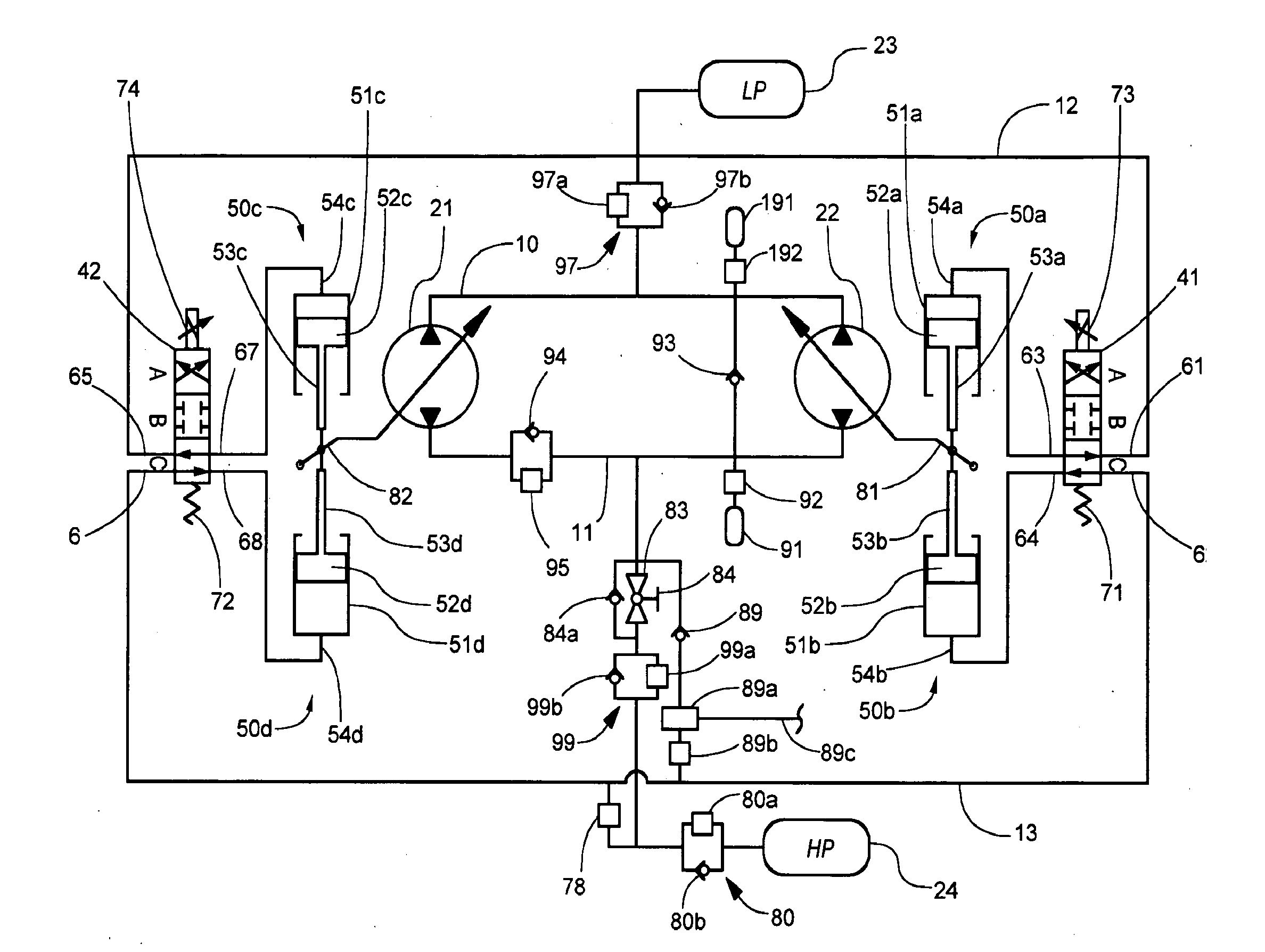
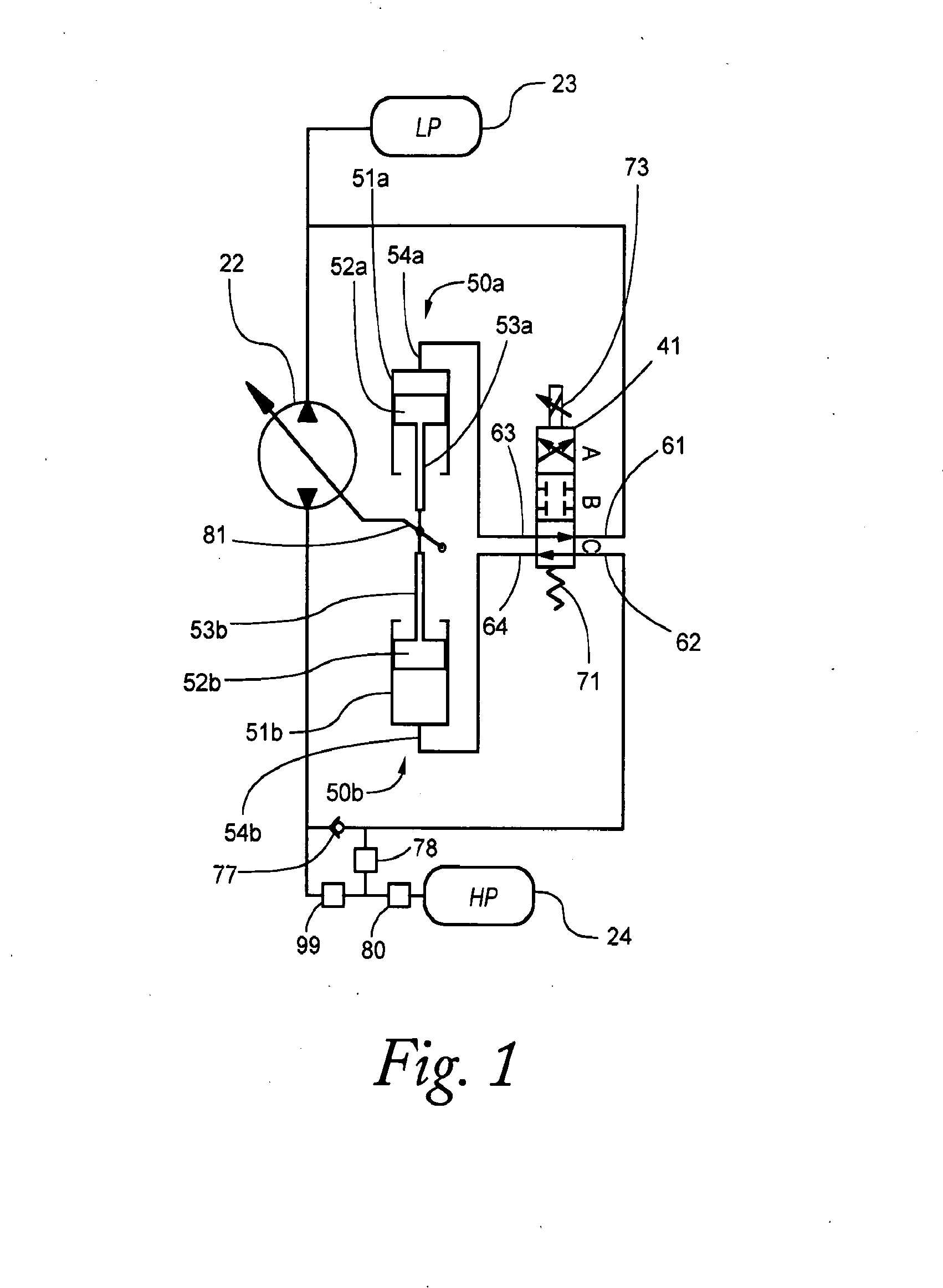
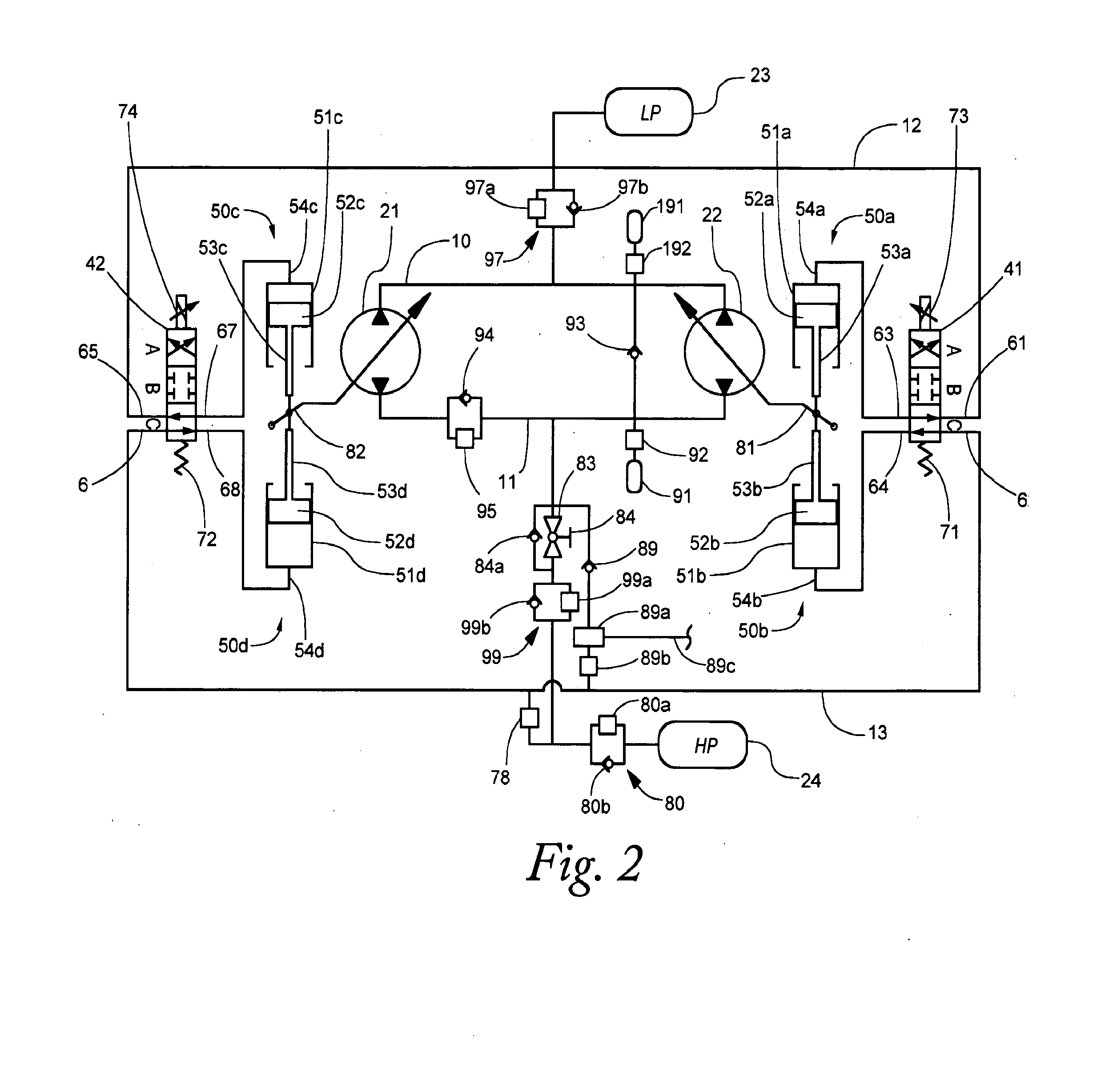
The invention is about a safe method for driving a hydraulic hybrid vehicle that uses over-center hydraulic pump / motors. The goal is to prevent the vehicle from losing control and causing damage or injury. The method includes default settings for displacement control, prevention of catastrophic over-pressurization, safe shutdown and startup of the vehicle, and a failsafe method that is cost-effective. The invention ensures the vehicle operates safely and efficiently in failure modes.

Problems solved by technology

Such valves are a significant source of pressure drop in fluid supply due to the convoluted channels the fluid must pass through.
They may also create undesirable noise when switched from one mode to another.
It must be assumed that, over the lifetime of the vehicle, there will be malfunctions in the mechanical and electrical systems.
Of particular concern is a loss of control over displacement of a pump / motor.
Because the displacement determines the power being transmitted by the device, a loss of control over displacement could have the effect of accelerating or braking the vehicle in an uncontrolled manner, potentially causing harm to the occupants and / or to the vehicle and its components.
Therefore it can be seen that a loss of control over displacement could be caused by an electronic control failure, or by a physical failure such as a hydraulic or mechanical malfunction.
An electronic control failure can result from a loss of electrical power or loss of electronic command signals.
For example, if the vehicle controller were to lose electrical power and was no longer issuing commands to the displacement control, or if the circuit relaying the commands were to fail, or if the electrical coil of a solenoid controlling the fluid switching valve were to fail, then control over displacement would be lost.
However, because the zero displacement position of an over-center pump / motor is mechanically indefinite, there may be some concern about the reliability of reaching this position, given that one form of failure has already occurred.
A physical failure is an even more fundamental concern, as it would result in total loss of control over displacement, even if the electronic controller and electrical command circuits were fully functional.
Either behavior would present an unacceptable safety hazard.
Providing such a valve for each pump / motor adds to the overall cost of the system, reduces its efficiency by presenting additional flow restrictions, and increases the number of controls that the controller must manage.
Therefore on startup, high pressure must only be restored to the circuit if it is certain that the drive pump / motor has remained at zero displacement; otherwise the vehicle may begin to accelerate unexpectedly when pressure is restored, or the engine pump may begin to turn the engine.

Method used


Image

  • Methods for Safe Operation of Hydraulic Hybrid Vehicles with Over-Center Pump/Motors
  • Methods for Safe Operation of Hydraulic Hybrid Vehicles with Over-Center Pump/Motors
  • Methods for Safe Operation of Hydraulic Hybrid Vehicles with Over-Center Pump/Motors

Examples


second embodiment

[0121]The following discussion discloses embodiments of a safe shutdown and startup procedure. In a first preferred embodiment, the previously described yoke latching means holds the over-center pump / motor(s) at zero displacement between shutdown and startup. In a second embodiment, the high pressure actuator feed is separately accessed as previously described so that the pump / motor(s) may be commanded to zero displacement if necessary prior to startup.

first embodiment

[0122]In the first embodiment, on shutdown, each pump / motor is verified to be at zero displacement and its latching means engaged to hold it at zero displacement. The main high pressure valve is then closed and confirmed by monitoring the resultant bleed-down in the high pressure lines. The low pressure source is then closed to outflow and power is removed from the actuator spool control solenoid.

[0123]This process is more precisely related in FIG. 7. Normally it would be expected that, for any vehicle, the shutdown process would be preceded by the driver bringing the vehicle to a stop and placing a mode lever (e.g., such as a gear shift lever having positions P-R-D-L) to a Park position (500) (optionally thereby engaging a parking pawl to further immobilize the vehicle), and engaging a parking brake (505). The driver would then turn the ignition key to an Off position (510), indicating to the vehicle controller that the vehicle should be shut down. According to the invention, this ...


PUM


Abstract

Fail-safe methods for utilizing an over-center pump / motor in a hydraulic hybrid vehicle are disclosed. A high-pressure fluid shutoff valve and an optional electrically or manually operated valve are additionally provided as means to ensure disconnection of the high pressure source in the event of a failure. Displacement stroke position and pressure differentials across the pump / motor are continually monitored. On detection of various modes of failure or irregularity in control of displacement, actions are taken including any of: the high pressure and low pressure accumulators are shut off automatically or manually, a check valve between the high and low pressure ports of the pump / motor is activated, and a small amount of pressurized fluid is released from the high pressure circuit to depressurize the captive fluid. Safe startup and shutdown procedures are also specified. The system provides for safe operation of a hydraulic hybrid vehicle that includes an engine pump and drive motor, at least one of which operates over-center. The system optionally provides a displacement control valve that is controlled by feedback from an actuator or displacement position sensor and that on loss of electric power to the displacement control valve will cause the controlled pump / motor to stroke to a zero displacement position.

Description

BACKGROUND OF THE INVENTION[0001]1. Technical Field[0002]The disclosed embodiments are directed generally to fluid power systems employing over-center motors, and, in particular, to fail-safe operations that are configured to remove output torque from a fluid motor in the event of a malfunction in the associated system.[0003]2. Description of the Related Art[0004]In recent years, significant interest has been generated in hybrid vehicle technology as a way to improve fuel economy and reduce the environmental impact of the large number of vehicles in operation. The term hybrid is used in reference to vehicles employing two or more power sources to provide motive energy to the vehicle. For example, hybrid electric vehicles are currently available that employ an internal combustion engine and a generator, which generates electricity to be stored in a battery of storage cells. This stored power is then used, as necessary, to drive an electric motor coupled to the drive-train of the vehi...

Claims


Application Information

Patent Timeline
IPC IPC(8): B60W10/30B60K6/22B60W20/00
CPCB60K6/12B60W10/04Y02T10/6282B60W50/038Y02T10/6208B60W10/06Y02T10/62F15B1/024F15B1/033F15B20/002F15B20/004F15B20/008F15B2211/20553F15B2211/212F15B2211/8626F15B2211/87F15B2211/8752F15B2211/8755F16H61/4192F16H61/421F16H61/439
Inventor GRAY, JR., CHARLES L.
Owner ENVIRONMENTAL PROTECTION AGENCY US
Learn More