

Atomic oscillator and method for fabricating atomic oscillator
a technology of atomic oscillators and masers, which is applied in the direction of oscillator generators, pulse automatic control, masers, etc., can solve the problems of short-term stability degraded frequency
- Summary
- Abstract
- Description
- Claims
- Application Information
AI Technical Summary
Benefits of technology
Problems solved by technology
Method used
Image

Examples
first embodiment
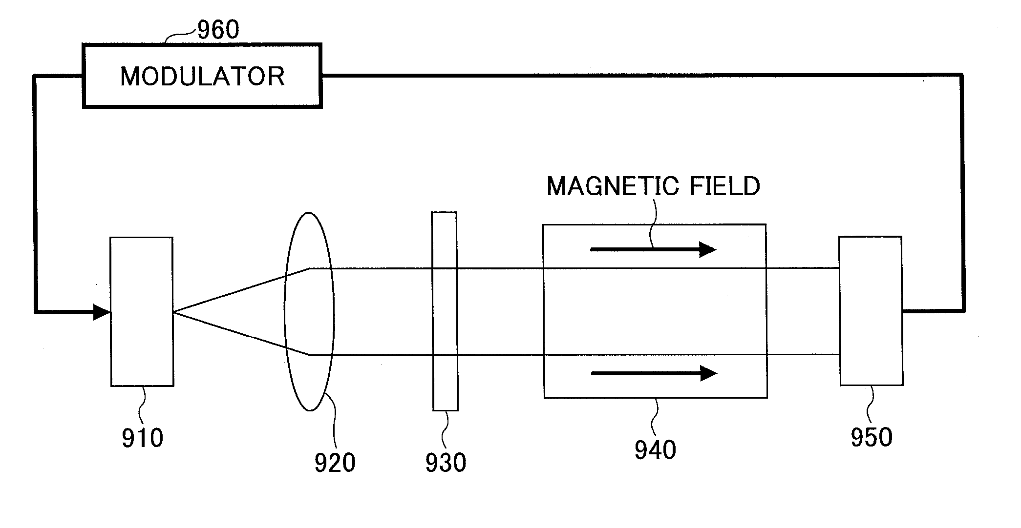
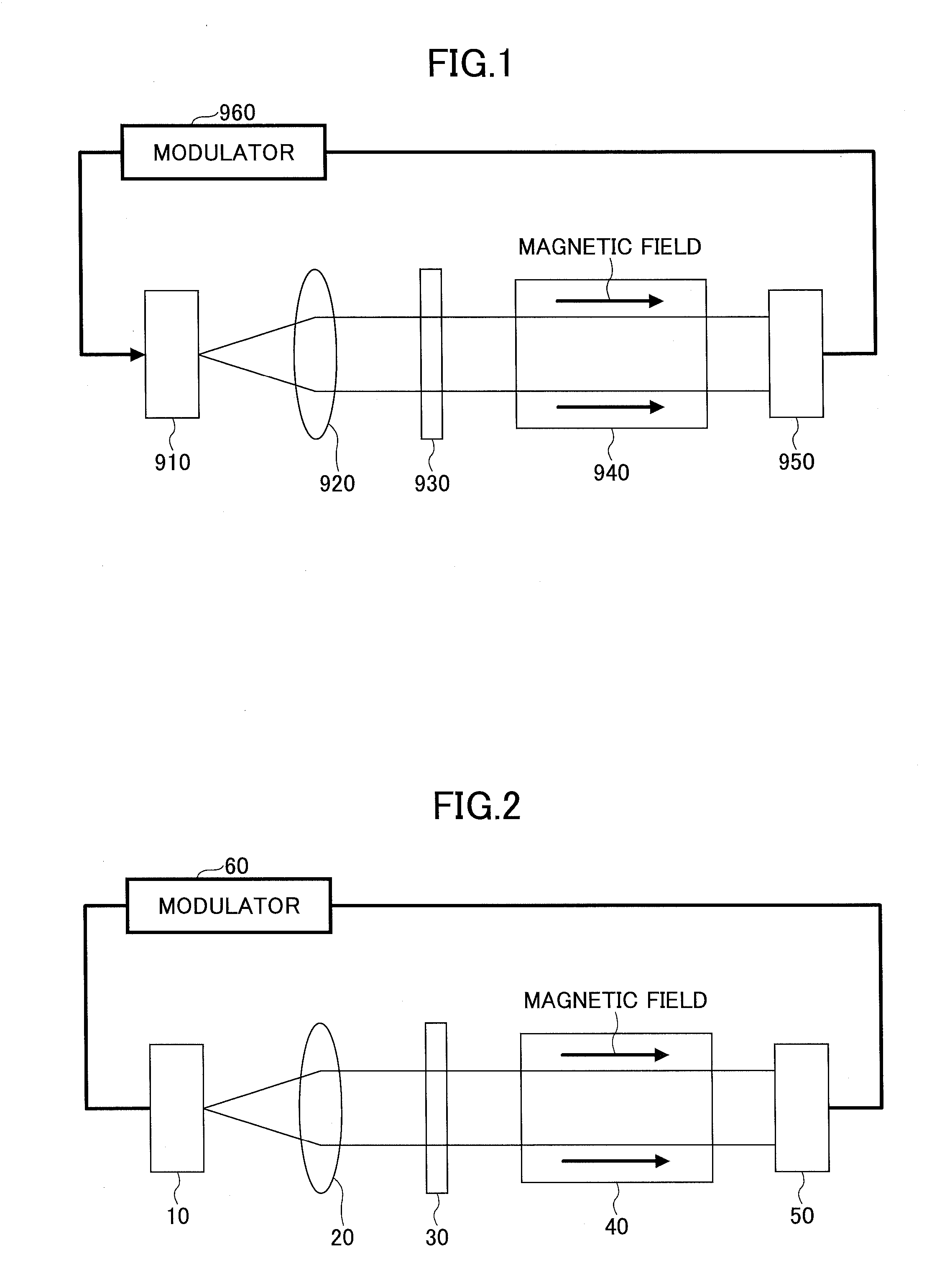
[0043]Anatomic oscillator and a method for fabricating the atomic oscillator in a first embodiment will be described. As illustrated in FIG. 2, the atomic oscillator in the first embodiment is regarded as a miniaturized atomic oscillator of a Coherent Population Trapping (CPT) method and includes a light source 10, a collimator lens 20, a λ / 4 plate 30, an Alkaline metal cell 40, a light detector 50, and a modulator 60.
[0044]For the light source 10, a laser element of a surface emitting laser element or the like may be used. Cs (Caesium) atom gas is enclosed by the Alkaline metal cell 40 as the Alkaline metal. A photodiode may be used for the light detector 50.
[0045]In the atomic oscillator in the first embodiment, light emitted from the light source 10 is irradiated to the Alkaline metal cell 40 through the collimator lens 20 and the λ / 4 plate 30, and electrons in the Alkaline metal atom are excited. The light passing through the Alkaline metal cell 40 is detected by the light detec...
second embodiment
[0063]Next, a second embodiment will be described. In the second embodiment, an atomic oscillator including an Alkaline metal cell different from the first embodiment and a method for fabricating the same will be described with reference to FIG. 4A through FIG. 4H. In FIG. 4A through FIG. 4H, elements that are the same as those illustrated in the previously described figures are indicated by the same reference numerals and the explanation thereof will be omitted.
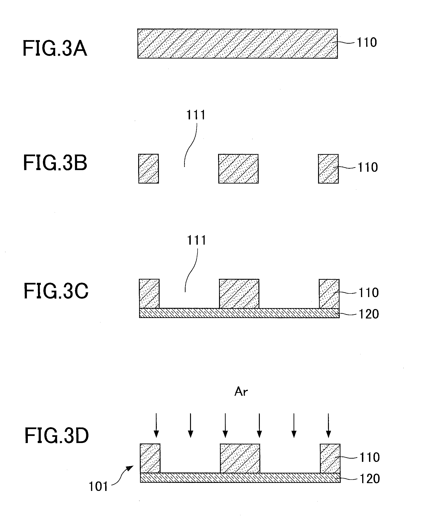
[0064]First, as illustrated in FIG. 4A, the Si substrate 110 is prepared. The Si substrate 110 is 1 mm in thickness and both sides thereof are mirror-finished. In the second embodiment, as described later, by bonding two Si substrates 110, the Alkaline metal cells are formed. Thus, two Si substrates 110 are prepared.
[0065]Next, as illustrated in FIG. 4B, a metal film 210 is formed in a predetermined area of one surface of one Si substrate 110. The metal film 210 is formed in areas other than areas where the opening parts 111...
third embodiment
[0080]Next, the third embodiment will be described. In the third embodiment, an atomic oscillator including Alkaline metal cells different from those in the first and second embodiments and a method for fabricating the same will be described with reference to FIG. 6A through FIG. 6H. In FIG. 6A through FIG. 6H, elements that are the same as those illustrated in the previously described figures are indicated by the same reference numerals and the explanation thereof will be omitted.
[0081]First, as illustrated in FIG. 6A, the Si substrate 110 is prepared. The Si substrate 110 is 1 mm in thickness, and both sides thereof are mirror-finished. In the third embodiment, as described later, since three Si substrates are bonded to form the Alkaline metal cell, three Si substrates 110 are prepared.
[0082]Next, as illustrated in FIG. 6B, the opening parts 111 are formed to each of three Si substrates 110. Specifically, the photo-resist is coated on one surface of each of the Si substrates 110. ...
PUM
| Property | Measurement | Unit |
|---|---|---|
| distance | aaaaa | aaaaa |
| voltage | aaaaa | aaaaa |
| voltage | aaaaa | aaaaa |
Abstract
Description
Claims
Application Information