
Impeller arrangement

a technology of impeller and inlet, which is applied in the direction of machines/engines, liquid fuel engines, and turbine growth, etc., can solve the problem of reducing the inlet efficiency of the impeller

Inactive Publication Date: 2013-01-17
BLACK & DECKER INC
View PDF2 Cites 16 Cited by
  • Summary
  • Abstract
  • Description
  • Claims
  • Application Information

AI Technical Summary

Benefits of technology

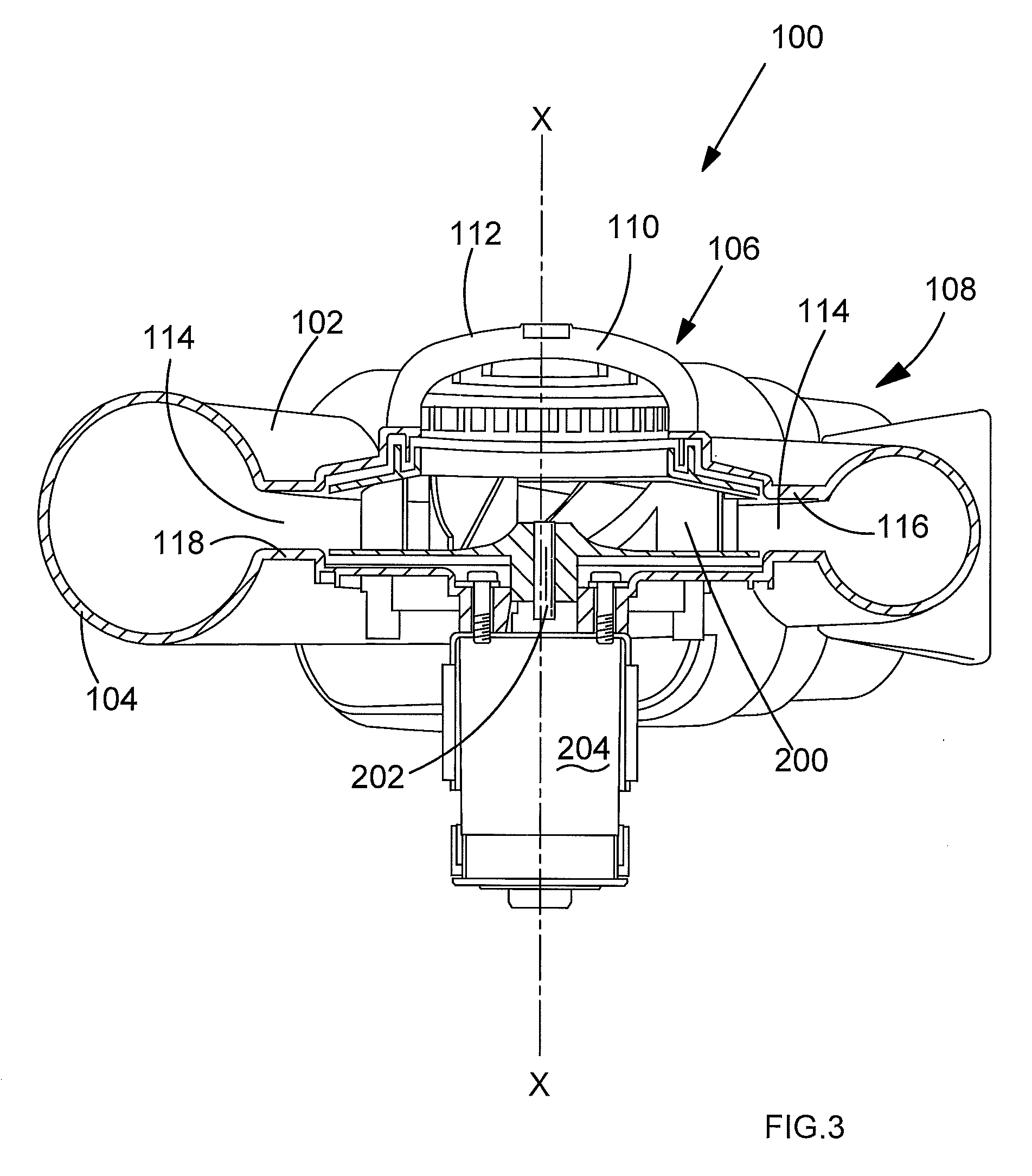
The present invention provides an improved impeller arrangement for a vacuum pump. An additional barrier arrangement is added near the impeller inlet to prevent air leaks and reduce inlet losses. This arrangement creates a convolved path between the impeller and the housing, which causes the airflow to change direction numerous times, resulting in reduced airflow bleeding and improved inlet efficiency of the impeller.

Problems solved by technology

This may reduce the inlet efficiency of the impeller because not all of the air admitted through the volute inlet passes through the impeller.

Method used


Image

  • Impeller arrangement
  • Impeller arrangement
  • Impeller arrangement

Examples


Embodiment Construction

[0035]The present invention provides an impeller and volute arrangement which reduces inlet losses to the impeller when compared to known arrangements. A barrier arrangement provided on the shroud of an impeller is located in close relationship with a complementary portion of the volute adjacent the air inlet.

[0036]The interaction between these components defines a convoluted or labyrinthine pathway between the shroud and the volute housing, reducing the likelihood of air passing there between and improving the flow of air into the eye of the impeller.

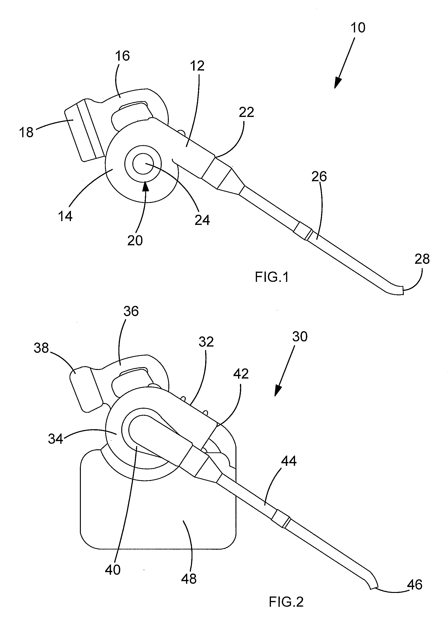
[0037]The general configuration of a blower appliance and a blower vacuum appliance will now be described with reference to FIGS. 1 and 2.

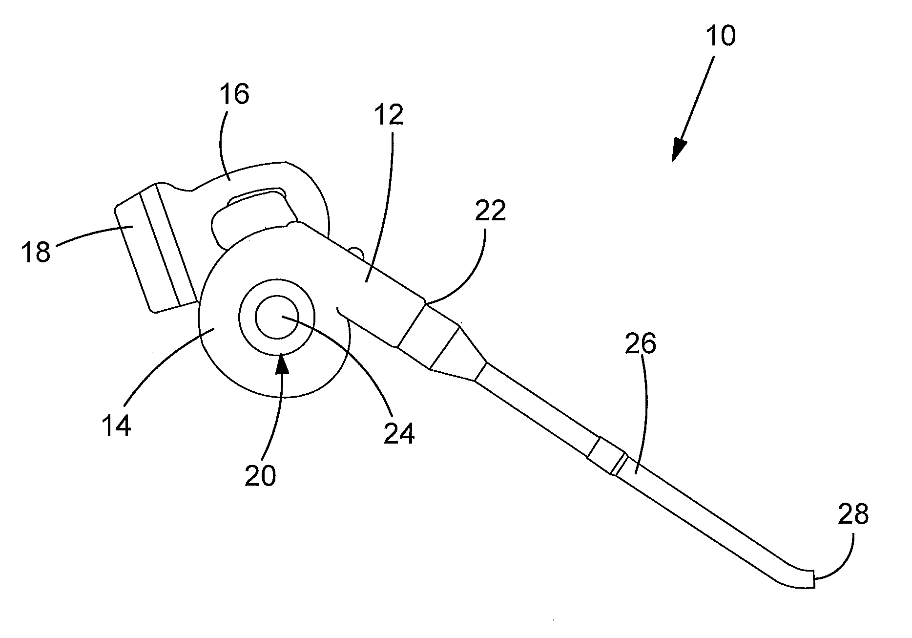
[0038]FIG. 1 shows an example of a blower (or sweeper) appliance 10 in which embodiments of the present invention may be used. The blower appliance 10 is an electrically-powered appliance which comprises a battery pack. However, alternatively the blower appliance 10 may be mains-powered or comprise a...


PUM


Abstract

An impeller arrangement for location for use with a blower and / or vac device, the impeller being rotatable about an axis of rotation and comprising a base, a shroud and a plurality of blades located therebetween, the shroud comprising an impeller inlet defining a passageway to the plurality of blades, a barrier arrangement located adjacent the impeller inlet to restrict airflow between the impeller and its housing. By providing such an arrangement, inlet losses to the impeller can be reduced when compared to known arrangements. The interaction between these components forms a barrier to bleeding of the airflow away from the inlet, reducing the likelihood of air passing between the impeller and its housing and improving the inlet efficiency of the impeller.

Description

TECHNICAL FIELD[0001]The present invention relates to an impeller arrangement. More particularly, an impeller arrangement for blower vacuums, vacuums and / or blower appliances.[0002]In general, blower vacuum appliances comprise a motor and fan arrangement. The motor is usually either petrol or electrically powered. The fan comprises a centrifugal impeller enclosed within a toroidal enclosure known as a volute. The impeller is configured, in use, to draw air in along the axis of rotation towards the centre or “eye” of the impeller and expel air out radially. The volute comprises a fluid inlet surrounding the eye of the impeller and aligned with the axis of rotation of the impeller, and a fluid outlet located at a point on the periphery of the volute. The shape of the volute essentially directs the radially-moving air towards the fluid outlet.[0003]Blower vacuum appliances generally have two modes of operation: blowing and vacuuming. In the blowing mode, clean air is drawn into the vol...

Claims


Application Information

Patent Timeline
IPC IPC(8): F04D17/16
CPCF04D29/162A01G20/47
Inventor ARMSTRONG, JONATHANHILL, STEPHEN
Owner BLACK & DECKER INC
Learn More