Aircraft propeller blade

a propeller blade and aircraft technology, applied in the direction of machines/engines, other domestic objects, transportation and packaging, etc., can solve the problems of large weight, long time consumption, and difficult technique, and achieve the effect of small overall weigh

Active Publication Date: 2013-01-17
SN DETUDE & DE CONSTR DE MOTEURS DAVIATION S N E C M A
View PDF3 Cites 45 Cited by
  • Summary
  • Abstract
  • Description
  • Claims
  • Application Information

AI Technical Summary

Benefits of technology

[0007]It is therefore desirable to be able to have propeller blades for aircraft that ...

Problems solved by technology

Although propeller blades made of metal material present good mechanical strength, they nevertheless present the drawback of being relatively heavy.
That technique is very difficult and requires the ply stacking operations to be performed manually, which is lengthy and expensive.
In addition, the stratified structure is not optima...

Method used


Image

  • Aircraft propeller blade
  • Aircraft propeller blade
  • Aircraft propeller blade

Examples


Embodiment Construction

[0047]The invention applies in general to various types of propeller blade used in the engines of aircraft such as airplanes or helicopters. The invention finds an application that is advantageous but not exclusive in propeller blades of large dimensions that, because of their size, present considerable weight and have a significant impact on the overall weight of the engine of the aircraft.

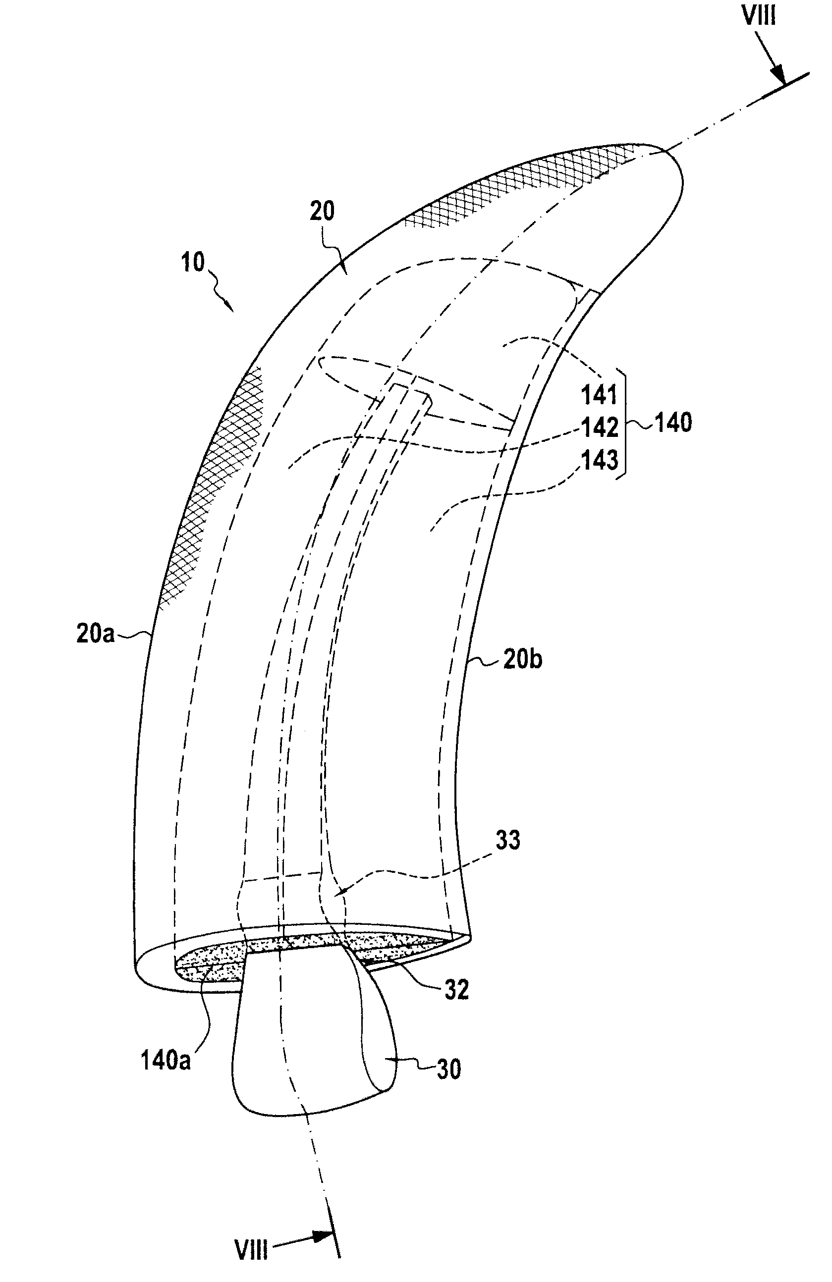
[0048]FIG. 1 shows a propeller blade 10 for mounting on an airplane turboprop, which propeller blade comprises, in well-known manner, an airfoil-profile structure 20 that is to form the airfoil portion of the blade, a root 30 formed by a thicker portion, e.g. having a bulb-shaped section extended by a tang 32. The airfoil-profile structure 20 presents, in cross-section, a curved profile of thickness that varies going from its leading edge 20a to its trailing edge 20b.

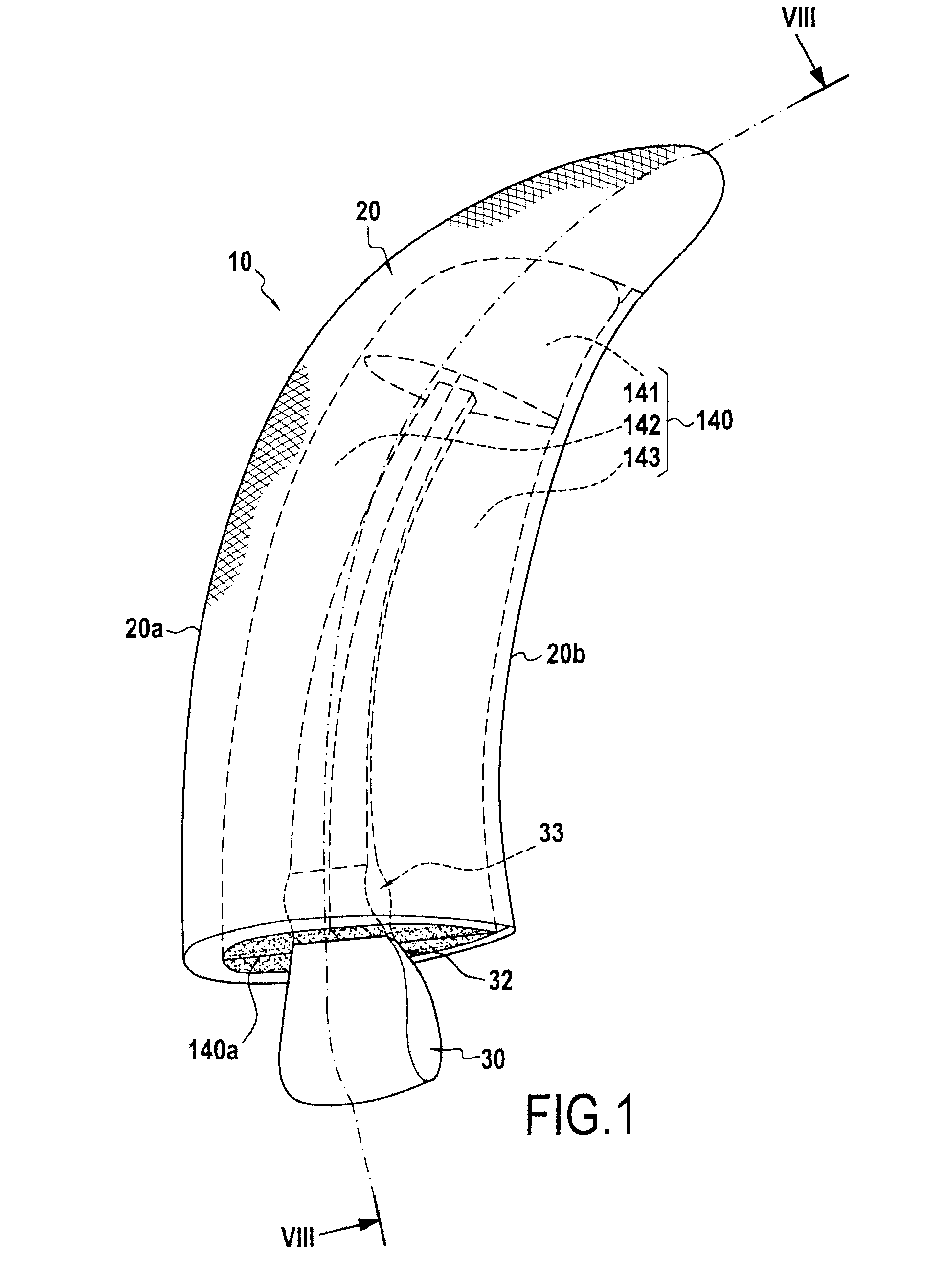
[0049]As shown in FIG. 2, the blade 10 is mounted on a rotor 51 of a turboprop 50 by engaging the root 30 in a housing formed in t...


PUM

PropertyMeasurementUnit
Thicknessaaaaaaaaaa
Shapeaaaaaaaaaa
Weightaaaaaaaaaa

Abstract

An aircraft propeller blade including an airfoil-profile structure. The airfoil-profile structure includes at least one fiber reinforcement obtained by three-dimensional weaving of yarns and densified by a matrix, and a shaping part made of cellular rigid material of determined shape, the reinforcement including at least two halves linked together by continuous weaving in the leading edge of the propeller blade, the two halves fitting tightly around the shaping part.

Description

BACKGROUND OF THE INVENTION[0001]The present invention relates to the field of propeller blades for aircraft, such as the blades present on turboprops.[0002]Propeller blades for turboprops are generally made of a metal material. Although propeller blades made of metal material present good mechanical strength, they nevertheless present the drawback of being relatively heavy.[0003]In order to obtain propeller blades that are lighter, it is known to make propeller blades out of composite material, i.e. by making structural parts out of fiber reinforcement with a resin matrix.[0004]The technique generally used consists in forming a stack of preimpregnated unidirectional sheets or plies (draping) that is placed in a mold with the successive plies being given different orientations, prior to compacting and polymerizing in an autoclave. An example of how a propeller blade can be made by that technique is described in particular in document U.S. Pat. No. 6,666,651.[0005]That technique is v...

Claims


Application Information

Patent Timeline
IPC IPC(8): B64C11/20B29C70/24
CPCB64C11/26B29C70/24B29C70/86B29C70/72B29L2031/087B29L2031/082B29D99/0025F01D5/282
Inventor COUPE, DOMINIQUEDAMBRINE, BRUNO JACQUES GERARDMAHIEU, JEAN-NOEL
Owner SN DETUDE & DE CONSTR DE MOTEURS DAVIATION S N E C M A
Why Eureka
Try Eureka