Removable Clip With User Interface

a technology of user interface and user interface, which is applied in the direction of portable computer details, electrical apparatus casings/cabinets/drawers, instruments, etc., can solve the problems of clip undesired interference with display, underutilization of clip real estate, and undesirable underutilization, so as to enhance the functionality and usability of existing devices, the user interface may be transparent

Active Publication Date: 2013-01-17
APPLE INC
View PDF23 Cites 66 Cited by
  • Summary
  • Abstract
  • Description
  • Claims
  • Application Information

AI Technical Summary

Benefits of technology

[0006]Embodiments of the present invention generally concern systems, apparatus's, and methods for providing a removable clip with a user interface to electronic computing devices. In one embodiment, the user interface may be configured to operate as a clip, thereby enabling the electronic computing device to be removably attached to an object such as a person's clothing. The user interface may also be operable to receive user inputs (via, e.g., a touch pad) and thereby control an electronic computing device. In some embodiments, the user interface may be transparent. As a result, information such as icons displayed on the electronic computing device may be visible to the user via the transparent user interface. The electronic computing device may then be responsive to user engagement with the clip based on locations of the user engagement and their correspondence to the icons displayed on the electronic computing device. In this fashion, a portable user interface may be provided that significantly enhances the functionality and usability of existing devices, and in some cases may also advantageously operate as a clip.

Problems solved by technology

In such cases, the clips are necessarily provided on a surface of the device other than the surface having the display, since doing otherwise would result in the clip undesirably interfering with the display.
Such a unit necessarily has a thicker width than the electronic computing device alone, which is in many cases disadvantageous for marketing purposes.
While today's clips provide a valuable function for portable electronic computing devices, they are deficient in that the real estate used by the clips is underutilized in that the clips are only used to attach electronic computing devices to other objects.
Such underutilization is particularly undesirable as technology continues to miniaturize since even the smallest amount of real estate used by a device is often considered burdensome by a consumer.

Method used


Image

  • Removable Clip With User Interface
  • Removable Clip With User Interface
  • Removable Clip With User Interface

Examples


first embodiment

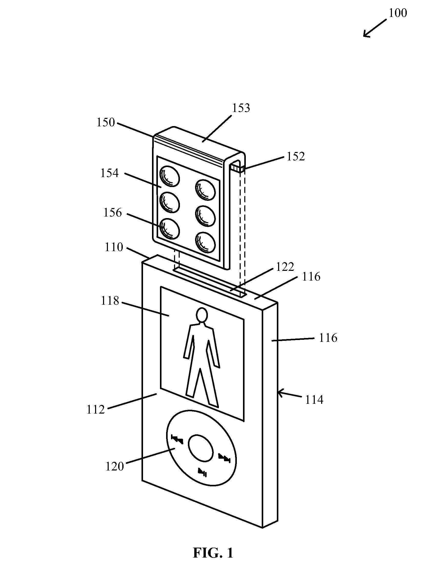
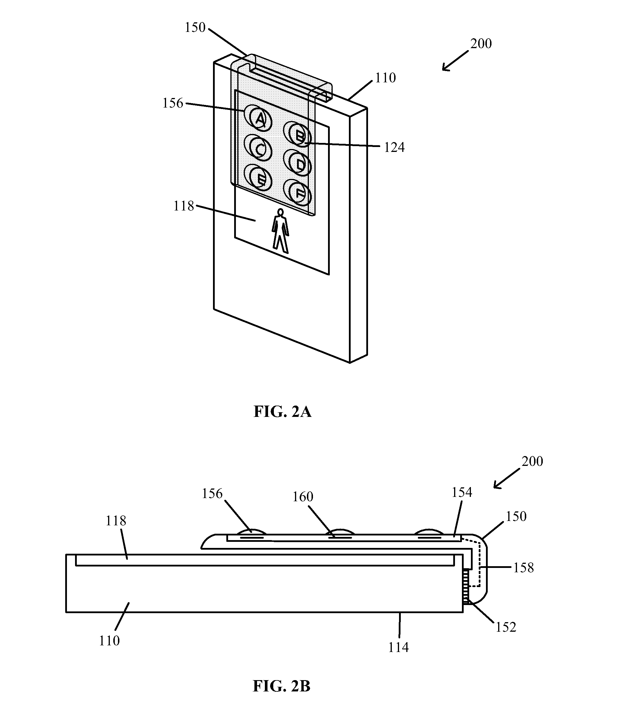
[0040]FIG. 1 illustrates a portable electronic system 100 according to a Portable electronic system 100 includes an electronic computing device 110 and a removable user interface 150.

[0041]According to this embodiment, electronic computing device 110 is a portable media player. For example, electronic computing device 110 may be an iPod as manufactured by Apple, Inc. of Cupertino, Calif.; a Microsoft Zune as manufactured by Microsoft Corp. of Redmond, Wash.; a Creative Zen as manufactured by Creative Technology Ltd. of Singapore; etc. According to other embodiments, electronic computing device 110 is not a portable media player. Rather, electronic computing device 110 may be any portable electronic computing device with a receptacle connector for establishing an electrical connection with other devices. For example, electronic computing device 110 may be a cellular phone, a personal digital assistant (PDA), a camera, a game player, a laptop computer, a netbook, a tablet, a booklet,...

second embodiment

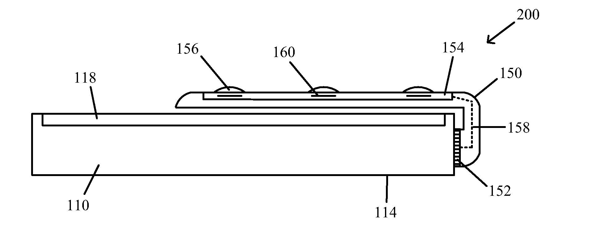
[0073]FIG. 4B shows a removable user interface 150 having a side profile according to a Removable user interface 150 according to this embodiment is similar to that discussed with reference to FIG. 4A, with the exception of bend portion 403.

[0074]Bend portion 403 according to this embodiment is square-shaped rather than curved. That is, bend portion 403 includes a first portion 403a arranged substantially perpendicular to interface portion 402, and a second portion 403b arranged substantially perpendicular to first portion 404a. As a result of providing plug 408 on second portion 403b, interface portion 402 may be oriented substantially parallel to a surface (e.g., front surface 112) of electronic computing device 110 when removable user interface 150 is engaged with electronic computing device 110.

third embodiment

[0075]FIG. 4C shows a removable user interface 150 having a side profile according to a Removable user interface 150 according to this embodiment is similar to that discussed with reference to FIG. 4B, with the exception of first portion 403a.

[0076]First portion 403a of bend portion 403 according to this embodiment is at an acute angle with respect to bottom surface 412. Second portion 403b is at an obtuse angle with respect to first portion 403a. Any suitable angles may be used so that interface portion 402 is oriented substantially parallel to a surface (e.g., front surface 112) of electronic computing device 110 when removable user interface 150 is engaged with electronic computing device 110. For example, the acute angle may be 45 degrees, and the obtuse angle may be 135 degrees. Any other combinations that sum to approximately 180 degrees (or 175 degrees, 178 degrees, etc.) may be used, and one skilled in the art could readily derive such combinations.


PUM


Abstract

Various embodiments of removable user interfaces, electronic computing devices, and systems are described. In one embodiment, an apparatus includes a body having a bend and a user interface area, a connector adapted to couple to a corresponding connector on an electronic device, and a plurality of conductive elements. The bend enables the user interface area to wrap around a portion of the electronic device when the connector is coupled to the corresponding connector on the electronic device. In another embodiment, a portable electronic system includes a removable user interface and an electronic computing device having a display surface, where the removable user interface is couplable to the electronic computing device such that the removable user interface is disposed over at least a part of the display surface.

Description

BACKGROUND[0001]1. Field of the Invention[0002]The present invention relates generally to removable clips with user interfaces. More particularly, the present invention relates to a clip that provides a user interface to an electronic computing device and is operable to selectively attach the device to an object.[0003]2. Description of the Related Art[0004]Various types of clips are provided today with portable electronic computing devices such as media players (e.g., music player or video player). The clips today typically serve only one function, which is to clip the device to various objects such as a person's clothing. As a result of such typical purposes of clips, clips usually only operate to mechanically connect the electronic computing device to another object. In some cases, the clips are used with electronic computing devices having electronic displays. In such cases, the clips are necessarily provided on a surface of the device other than the surface having the display, s...

Claims


Application Information

Patent Timeline
Patent Type & Authority Applications(United States)
IPC IPC(8): G06F3/048G06F1/16
CPCG06F1/1632G06F3/0488G06F2203/04809G06F1/1684G06F3/0489G06F3/0416G06F1/1607G06F1/1613G06F1/163G06F3/016H04M1/0256
Inventor ROTHKOPF, FLETCHER R.DABOV, TEODOR
Owner APPLE INC
Why Eureka
Try Eureka