Wire harness, wire harness manufacturing method

Inactive Publication Date: 2013-01-24
AUTONETWORKS TECH LTD +2
View PDF0 Cites 7 Cited by
  • Summary
  • Abstract
  • Description
  • Claims
  • Application Information

AI Technical Summary

Benefits of technology

The patent aims to provide a wire harness with a covering member that has improved abrasion resistance, regardless of whether the covering member is made of non-woven fabric or other materials. The method for manufacturing the wire harness should also prevent or suppress any increase in manufacturing cost or production steps. The invention also provides a tool for holding the covering member, which helps prevent unexpected deformation during the molding process.

Problems solved by technology

However, the structure to which the protector as an injection molded product is applied has the following problem.
Generally, as the injection molding die used for injection molding of a resin material is expensive, the equipment cost is increased, and the price of the shape maintenance member or the protector is high.
Accordingly, the manufacturing cost is increased, and the price of the wire harness may be increased.
Further, in the structure where the shell-type shape maintenance member or the protector is attached to a predetermined part of the trunk line or the branch line, in some cases, a gap exists between the electric wires included in the trunk line or the branch line and the inner peripheral surface of the shape maintenance member or the protector.
Accordingly, when vibration or impact is applied to the wire harness, the electric wires collide with the inner peripheral surface of the shape maintenance member or the protector, and an impulsive sound may occur.
The occurrence of such impulsive sound may degrade the quality of the vehicle or the like to which the wire harness is applied.
Further, there is a probability of damage by the collision of the electric wires with the inner peripheral surface of the shape maintenance member or the protector.
However, in this structure, a process to insert the shock-absorbing material inside the shape maintenance member or the protector is required.
Accordingly, the number of steps is increased, and the manufacturing cost may be increased.
Further, as the number of parts is increased, the cost of the parts may be increased.
Further, even a part of the protector formed of the non-woven fabric becomes wet, the liquid permeates inside the non-woven fabric.
Further, in comparison with a resin injection molded product, the non-woven fabric is soft and its abrasion resistance level is low.
Accordingly, when vibration or impact is applied when the vehicle or the like is used, there is a probability of abrasion of the protector formed of the non-woven fabric due to contact with another member (e.g., a vehicle body).
Especially upon application of vibration, the abrasion progresses due to intermittent contact or slide-contact between the protector with the other member.
In this manner, in comparison with the protector which is an injection molded product, the durability of the protector of the non-woven fabric is low.

Method used


Image

  • Wire harness, wire harness manufacturing method
  • Wire harness, wire harness manufacturing method
  • Wire harness, wire harness manufacturing method

Examples


first embodiment

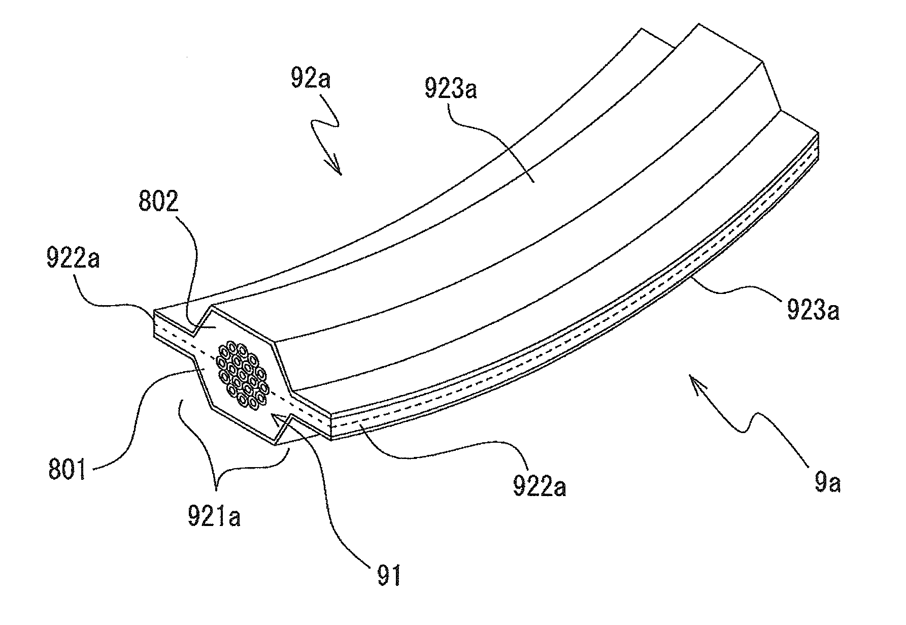
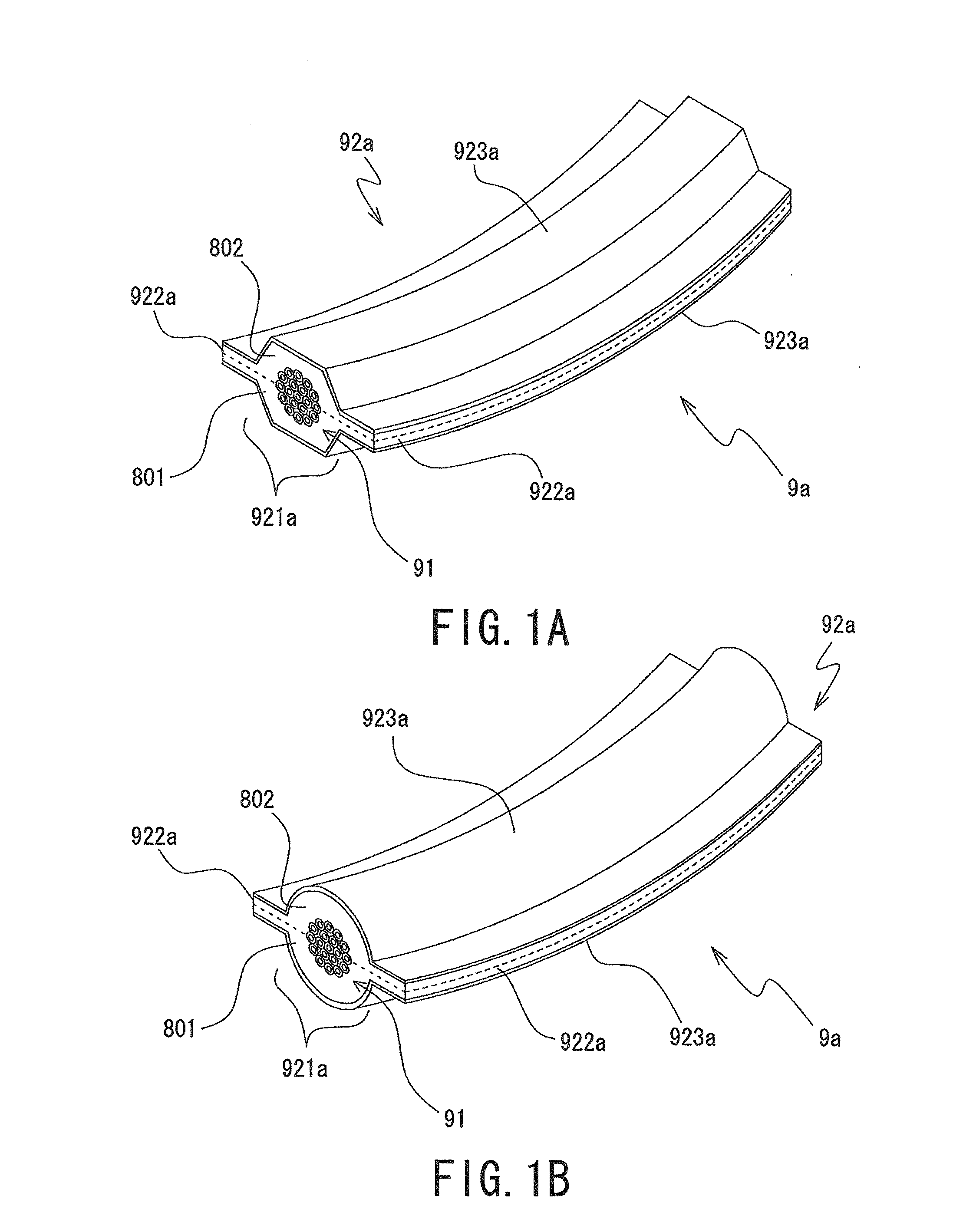
[0083]The covering member 92a provided in the wire harness 9a according to the present invention has a main body 921a, an extension part 922a and a protective layer 923a. The main body 921a and the extension part 922a are formed of two materials 801 and 802.

[0084]For the sake of convenience of explanation, one of the two materials of the main body 921a and the extension part 922a of the covering member 92a will be referred to as the “first material 801”, and the other material, the “second material 802”. In FIGS. 1A and 1B, a broken line along the cross section of the covering member 92a schematically indicates a joint surface (boundary) between the first material 801 and the second material 802.

[0085]The main body 921a of the covering member 92a covers a predetermined part of electric wires 91 (a predetermined part of trunk line and branch line of the wire harness 9a according to the first embodiment of the present invention) (in other words, the predetermined part of the electric ...

second embodiment

[0240]FIGS. 9A and 9B are external perspective diagrams of the predetermined part (the position in which the covering member 92b is provided) of the wire harness 9b according to the present invention. FIG. 9A shows a structure where the covering member 92b has an approximately hexagonal cross-sectional shape. FIG. 9B shows a structure where the covering member 92b has an approximately circular cross-sectional shape.

[0241]The covering member 92b of the wire harness 9b according to the second embodiment of the present invention has a similar structure to that of the main body 921a of the covering member 92a of the wire harness 9a according to the first embodiment of the present invention. Note that the covering member 92b of the wire harness 9b according to the second embodiment of the present invention, unlike the covering member 92a of the wire harness 9a according to the first embodiment of the present invention, has no extension part.

[0242]Note that in FIG. 9A, the covering member...

fourth embodiment

[0314]Further, it is preferable that the protective layer 923d provided on the covering member 92d of the wire harness 9d according to the present invention is formed of a material having a water proofing property or a water repellent property (a material which prevents permeation or transmission of liquid such as water).

[0315]Note that the protective layers 923c and 923d (the protective layer material 803) are formed of a material having thermoplasticity. When the first non-woven fabric is applied to the first material 801 and the second material 802, a material having a fusing point higher than that of the binder material of the binder fiber of the first non-woven fabric is applied to the protective layers 923c and 923d. For example, as the material of the protective layers 923c and 923d (the protective layer material 803), a mesh-type or sheet-type member formed of a polypropylene (PP) (fusing point is about 120° C.) is applicable. When the second non-woven fabric or foam formed ...


PUM


Abstract

A predetermined part of electric wires (91) is held or wrapped in a first material (801) and a second material (802) formed of a thermoplastic material, and a protective layer material (803) formed of a water repellent material is provided on approximately the entire surface of the first material and the second material. The first material (801), the second material (802) and the protective layer material (803) are heated and pressurized. The first material (801) and the second material (802) are molded to have a predetermined shape and size. The protective layer material (803) is joined to the surface of the first material and the second material (802) by melting at least a part of the surface layer of the first material (801) and the second material (802). Further, a material having high abrasion resistance is selected as the protective layer material (803).

Description

BACKGROUND OF THE INVENTION[0001]1. Field of the Invention[0002]The present invention relates to a wire harness and a wire harness manufacturing method, and more particularly, to a wire harness having a member to maintain electric wires in a predetermined shape and / or to protect the electric wires, and a wire harness manufacturing method.[0003]2. Description of the Related Art[0004]In a vehicle such as an automobile, a wire harness to mutually connect electric devices, electronic devices and the like is provided. A general wire harness has a predetermined number and a predetermined type of electric wires. These electric wires are bundled to form a trunk line or a branch line.[0005]In the wire harness, the trunk line and the branch line are arranged along a predetermined route inside the vehicle or the like. Accordingly, to facilitate the arrangement of the trunk line and the branch line of the wire harness, in some cases, the trunk line and the branch line of the wire harness are fo...

Claims


Application Information

Patent Timeline
IPC IPC(8): H02G3/04B32B37/06
CPCH01B13/01254H02G3/0487Y10T156/1043B60R16/0215H01B7/2825
Inventor MURATA, ATSUSHIHIRANO, NOBUYUKISATO, OSAMU
Owner AUTONETWORKS TECH LTD
Why Eureka
Try Eureka