Cooling Structure Of Supercharger

US20110154818A1Inactive Publication Date: 2011-06-30YANMAR POWER TECHNOLOGY CO LTD

Image

  • Cooling Structure Of Supercharger
  • Cooling Structure Of Supercharger
  • Cooling Structure Of Supercharger

Examples


Embodiment Construction

[0045]Next, explanation will be given on the mode for carrying out the invention.

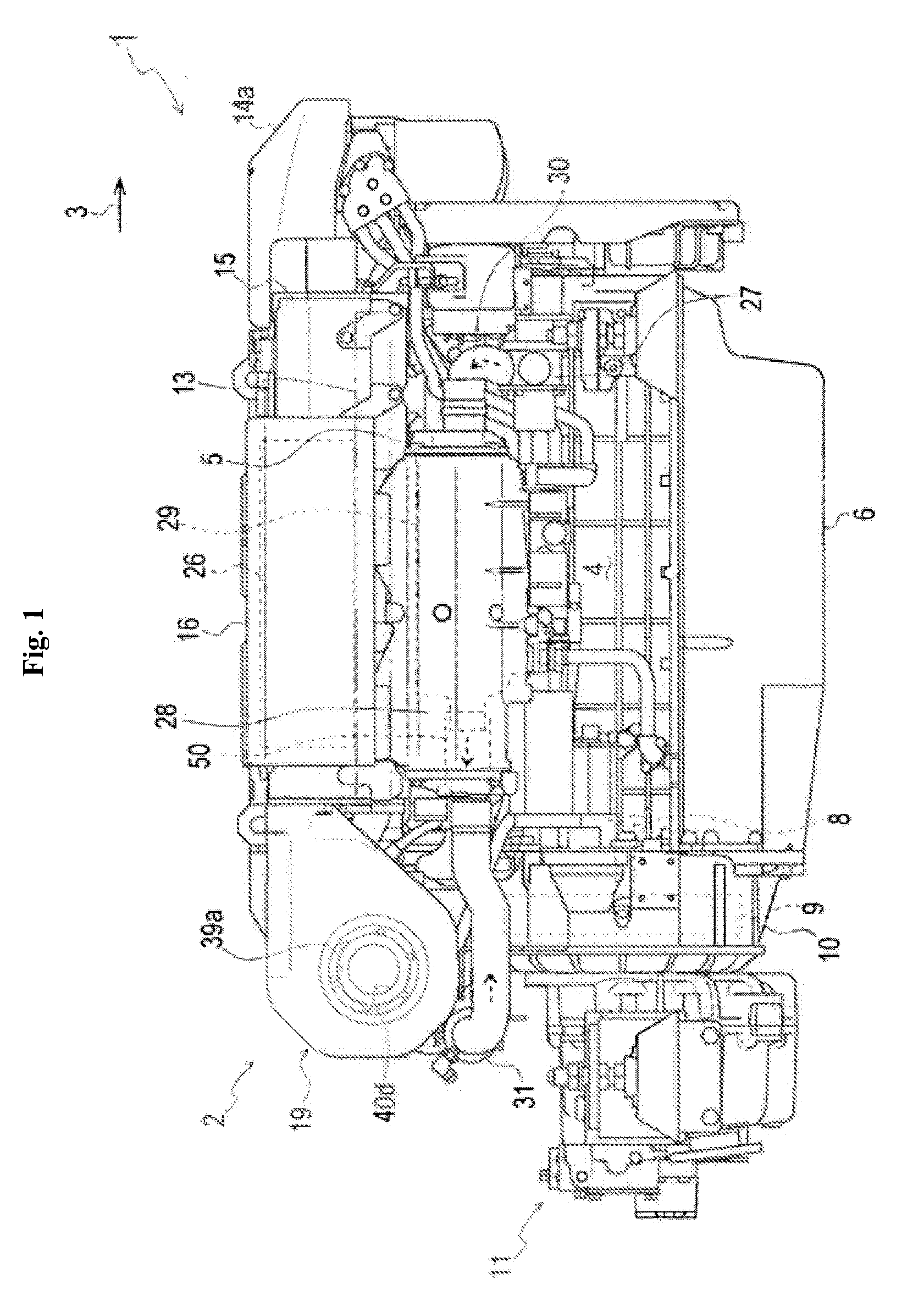
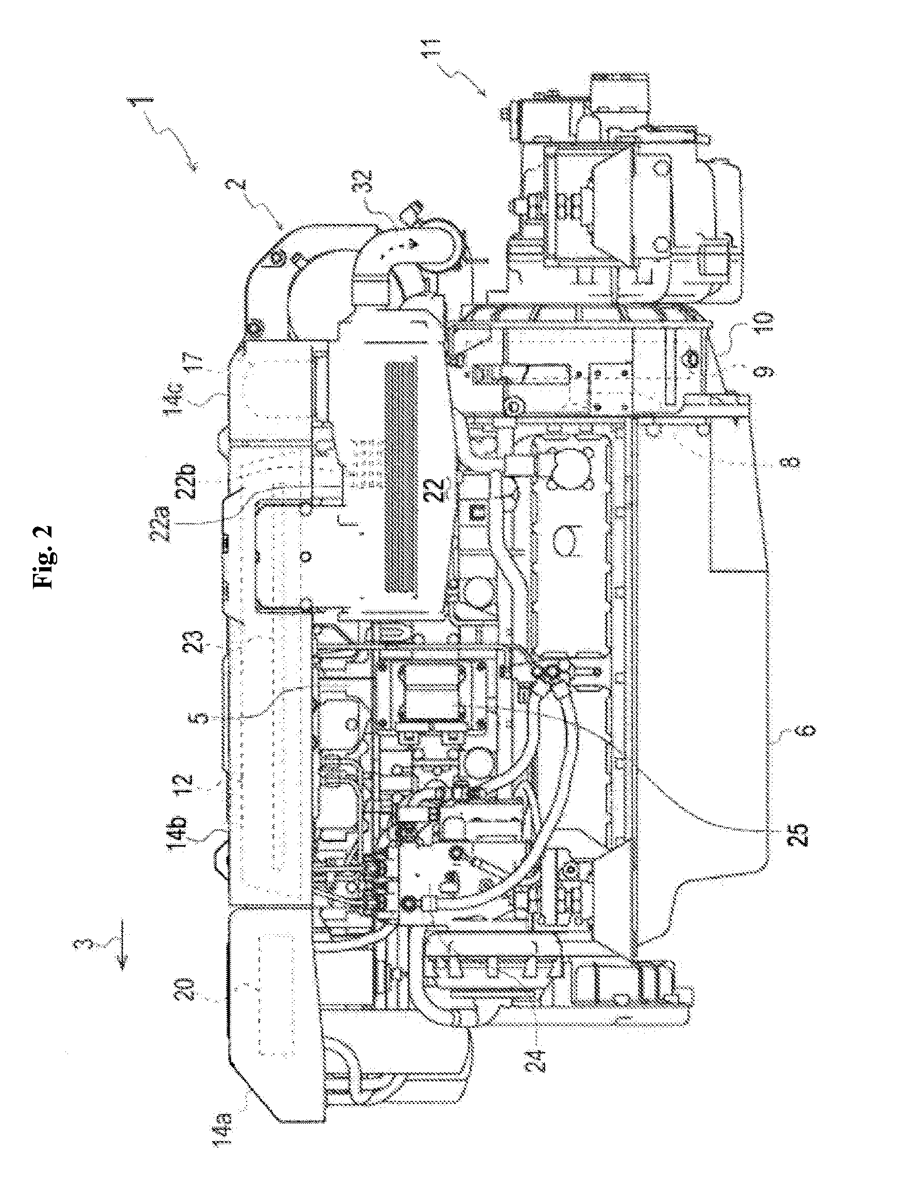
[0046]In below explanation, direction of a crankshaft of an engine 1 is regarded as the longitudinal direction, the output side of the engine 1 (at a side of a clutch 11 discussed later) is regarded as the rear, and the side opposite thereto (direction of an arrow 3 in FIG. 3) is regarded as the front. Furthermore, the direction perpendicular to the direction of the crankshaft of the engine 1 is regarded as the lateral direction, the right side when viewed from the rear (direction of an arrow 21 in FIG. 3) is regarded as the right, and the side opposite thereto is regarded as the left.

[0047]Firstly, explanation will be given on the entire construction of the engine 1 having a supercharger 2 according to the present invention referring to FIGS. 1 to 4.

[0048]The engine 1 has a cylinder block 4 which is extended longitudinally. A cylinder head 5 is provided at the upper end of the cylinder block 4, and an ...


PUM


Abstract

In order to reduce radiation heat from the turbine housing of a supercharger, the turbine housing is conventionally water-cooled or covered with a heat shielding material, but it is required to control heat loss due to excessive water cooling or high temperature on the outer surface of the heat shielding material. On the contrary, a solution by a cooling structure consisting of an inner thermal insulation portion of an air layer and an outer low temperature portion covering the inner thermal insulation portion has an inevitable problem of increasing number of components and upsizing. In a cooling structure of a supercharger (2) equipped with a turbine wheel (35) which rotates with exhaust gas from an engine (1) and provided, on the periphery of a turbine housing (40) for housing the turbine wheel (35), with a cooling structure (47) consisting of an inner thermal insulation portion of an air layer (45) and an outer low temperature portion covering the inner thermal insulation portion, the outer low temperature portion is constituted by integrally forming a circulation passage (46) of fresh water in a turbine cover (39) which covers and protects the turbine housing (40).

Description

TECHNICAL FIELD[0001]The present invention relates to a supercharger having a turbine wheel rotated by exhaust gas from an engine, especially a cooling structure of a supercharger in which a cooling structure body, which reduces certainly radiation heat to the circumference of the supercharger while preventing reduction of turbine efficiency caused by excessive cooling of a turbine housing in which the turbine wheel is housed, can be arranged in small space with few parts.BACKGROUND ART[0002]Generally, a supercharger is known in which a turbine wheel is rotated by exhaust gas from an engine so as to rotate an impeller via a turbine shaft constructed integrally with the turbine wheel, whereby sucked air (hereinafter, referred to as “intake air”) is compressed and sent to cylinders of a cylinder head. In the supercharger, temperature of a turbine housing in which the turbine wheel is housed is made very high by the heat of exhaust gas, therefore it is necessary to protect the other co...

Claims


Application Information

Patent Timeline
30 Jun 2011
Publication
US20110154818A1
IPC
F02C6/12
CPC
F01D25/145; F01D25/26; F01P3/207; F01P2050/06; F01P2060/02; F05D2220/40; F01P2060/12; F02B37/00
Inventors
TAKAHATA, TERUMITSU