
System and method for monitoring and controlling heating/cooling systems

a technology of heating/cooling system and monitoring system, applied in the field of thermal regulation system, can solve the problems of energy loss, many limitations of mechanical sensing, and extremely inaccurate methods

Inactive Publication Date: 2013-01-24
HACHAM SASSON YUVAL
View PDF16 Cites 29 Cited by
  • Summary
  • Abstract
  • Description
  • Claims
  • Application Information

AI Technical Summary

Benefits of technology

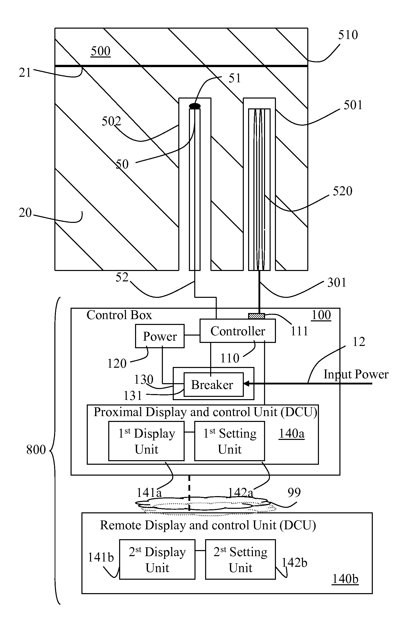
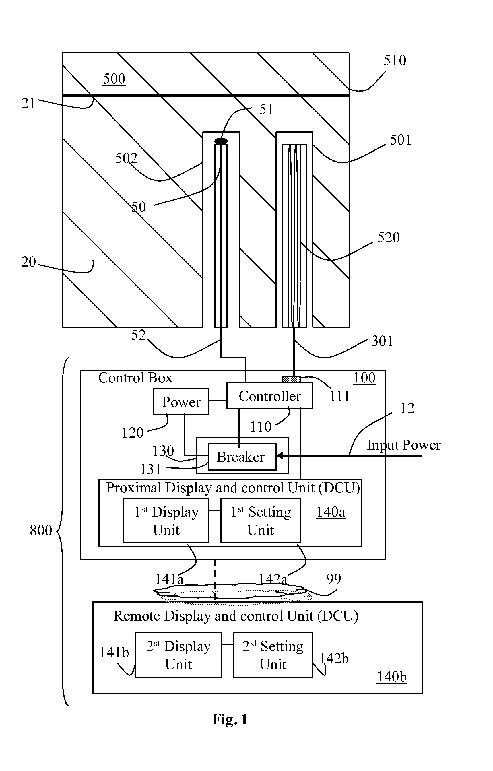
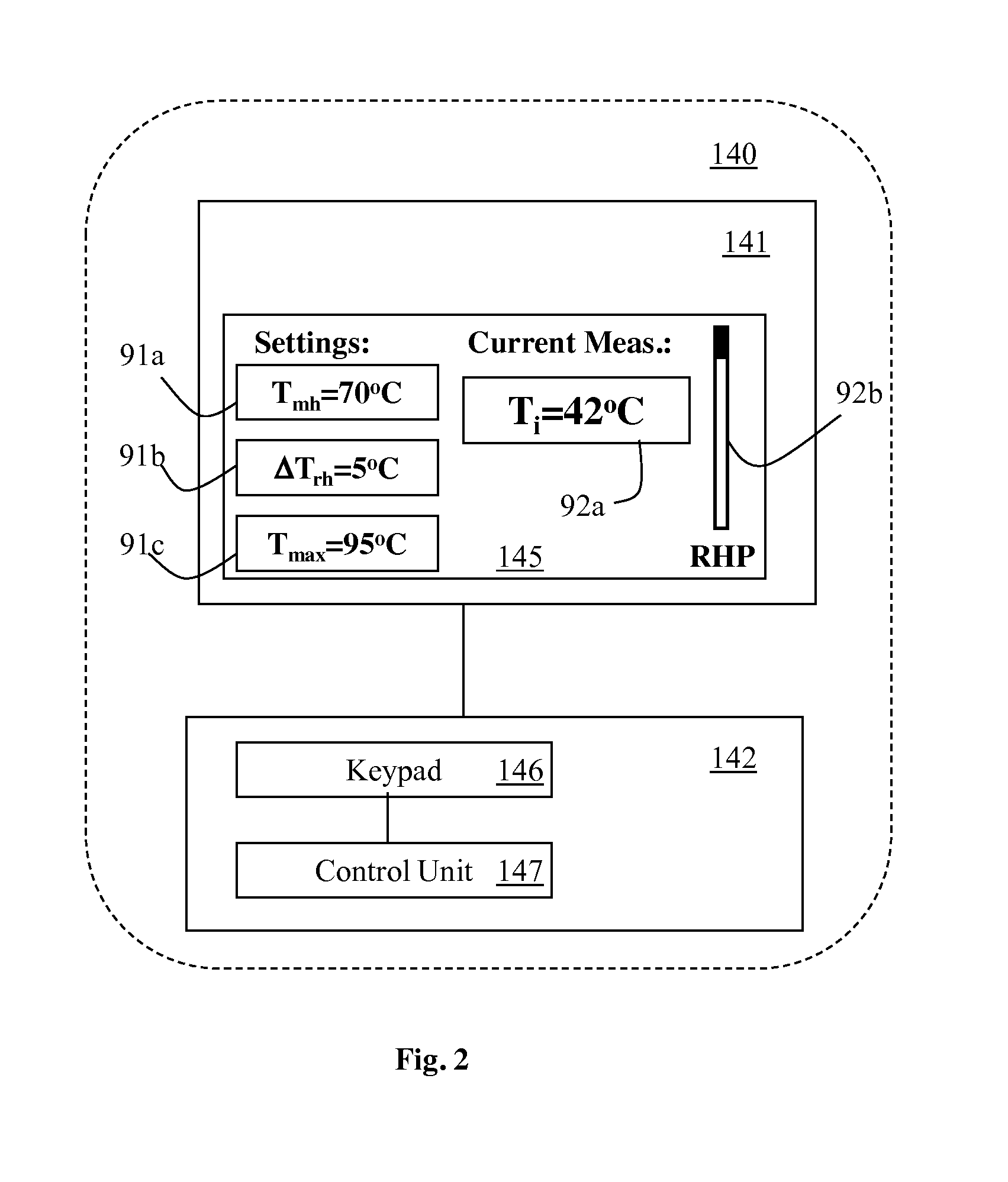
The invention is a monitoring and control system for thermal regulation systems (TRS) that can sense and control the temperature of a substance in the TRS. The system includes a controller that receives data from a sensor and analyzes it to determine if the temperature of the substance has reached a predefined threshold. If so, the controller will disconnect the TRS from its power supply to prevent damage or overload. The system also includes a display and control unit that allows users to set and change settings for the monitoring and control system. The monitoring and control system can be used in heating systems, such as water boilers, and can help prevent accidents and improve safety standards.

Problems solved by technology

Mechanical sensing has many limitations; one is that this method is extremely inaccurate since the plates do not respond to all changes in the same linear manner.
This may lead to errors in temperature measuring that may cause energy lose and / or, in some cases, allowing the water in the container to overheat.
Another downside is that these metal plates are easily eroded over time and change the manner in which they physically respond to temperature changes.
Another hazardous downside is that these metal plates do not respond the same to changes in temperature of air and therefore if the boiler tank is for some reason depleted or semi-depleted, the plates will not be able to sense that only the metal tank itself is heated, which may lead to an extremely dangerous explosion of the tank once water are poured back therein.

Method used


Image

  • System and method for monitoring and controlling heating/cooling systems
  • System and method for monitoring and controlling heating/cooling systems
  • System and method for monitoring and controlling heating/cooling systems

Examples


Embodiment Construction

[0025]In the following detailed description of various embodiments, reference is made to the accompanying drawings that form a part thereof, and in which are shown by way of illustration specific embodiments in which the invention may be practiced. It is understood that other embodiments may be utilized and structural changes may be made without departing from the scope of the invention.

[0026]At least one embodiment of the invention provides methods and systems for monitoring and controlling a thermal regulation systems (TRSs), which are heating and / or cooling systems such as water boilers, cooling radiators (e.g. for vehicles), heating radiators, central heating systems, and the like. These TRSs typically include one or more containers for containing and optionally circulating a liquid or a gas such as water, oil, etc. which carries the heat or cools another system and / or a predefined space in which it is installed.

[0027]At least one embodiment of the invention provides systems and...


PUM


Abstract

A monitoring and control system for monitoring and controlling at least one thermal regulation system (TRS), where the monitoring and control system includes a thermal sensor for sensing temperature in the TRS; a controller, operatively associated with the TRS and the thermal sensor, where the controller receives data from the thermal sensor including temperature measurements thereof and analyzes the data for allowing disconnecting TRS from its power supply once the temperature in the TRS, sensed by the sensor, reaches at least one predefined threshold; and a breaking mechanism, operatively associated with the controller, including at least one circuit breaker for allowing disconnecting the TRS from its power supply when identifying an electrical overload or once disconnected by the controller operatively associated therewith.

Description

CROSS-REFERENCE TO RELATED PATENT APPLICATIONS[0001]This application claims priority to Israeli patent application No. 214189 filed on Jul. 19, 2011, which is incorporated herein by reference in its entirety.FIELD OF THE INVENTION[0002]At least one embodiment of the invention generally relates to thermal regulation systems and more particularly to systems and methods for monitoring and controlling thermal regulation systems.BACKGROUND OF THE INVENTION[0003]Heating and / or cooling systems such as water boiler tanks, central heating systems, heating and / or cooling radiators and the like, are commonly used and often require temperature regulation and controlling for safety and / or energy saving purposes. In heating systems temperature regulation is necessary to prevent the liquid or gas running through the system from exceeding a threshold temperature to prevent damaging the system and / or even physically endangering people in the vicinity of the system. A water boiler, for example, requi...

Claims


Application Information

Patent Timeline
IPC IPC(8): F24H9/20F24H1/20
CPCF24H1/20F24H9/20G05D23/24F24H9/2021F24D2220/042F24H1/185F24H15/37F24H15/395F24H15/421F24H15/281F24H15/45F24H15/486F24H15/223F24H15/174F24H15/124
Inventor HACHAM, SASSON YUVAL
Owner HACHAM SASSON YUVAL
Learn More