
Device for turning sheet-like substrates

a technology of substrates and devices, applied in the direction of printing, instruments, transportation and packaging, etc., can solve the problems of high energy consumption for generating the required amount of air, high air consumption needed to generate a sufficient air cushion over the width impair the guidance accuracy of the substrate sheet, so as to achieve a lower air consumption for generating the air cushion

Inactive Publication Date: 2013-01-24
EASTMAN KODAK CO
View PDF3 Cites 1 Cited by
  • Summary
  • Abstract
  • Description
  • Claims
  • Application Information

AI Technical Summary

Benefits of technology

The technical effect of this patent is to provide a device that can turn a sheet-like substrate while reducing the air consumption needed to create an air cushion.

Problems solved by technology

A drawback of a design of this type is the high air consumption needed to generate a sufficient air cushion over the width of a substrate sheet.
A high air consumption of this nature is concomitant with correspondingly high energy consumption for generating the required air quantity.
In edge areas of the substrate sheet, there fluttering of the substrate sheet may also result from high air flows, which can impair the guidance accuracy of the substrate sheet.
Furthermore, a heavy noise development can result from this and / or from strong air flows.
The guidance accuracy can be impaired by repeated turning of print material sheets in a turning unit of the above type.

Method used


Image

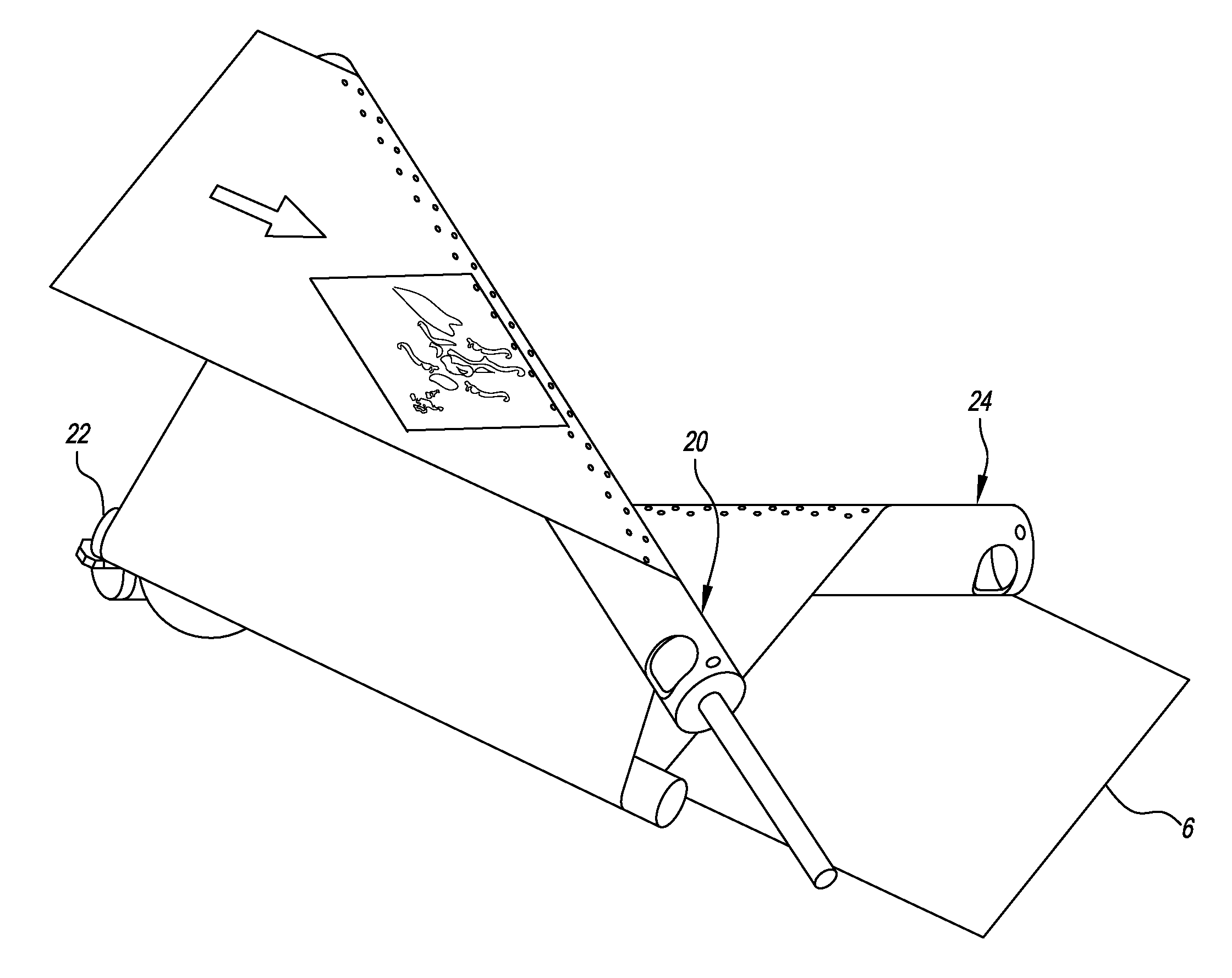
  • Device for turning sheet-like substrates
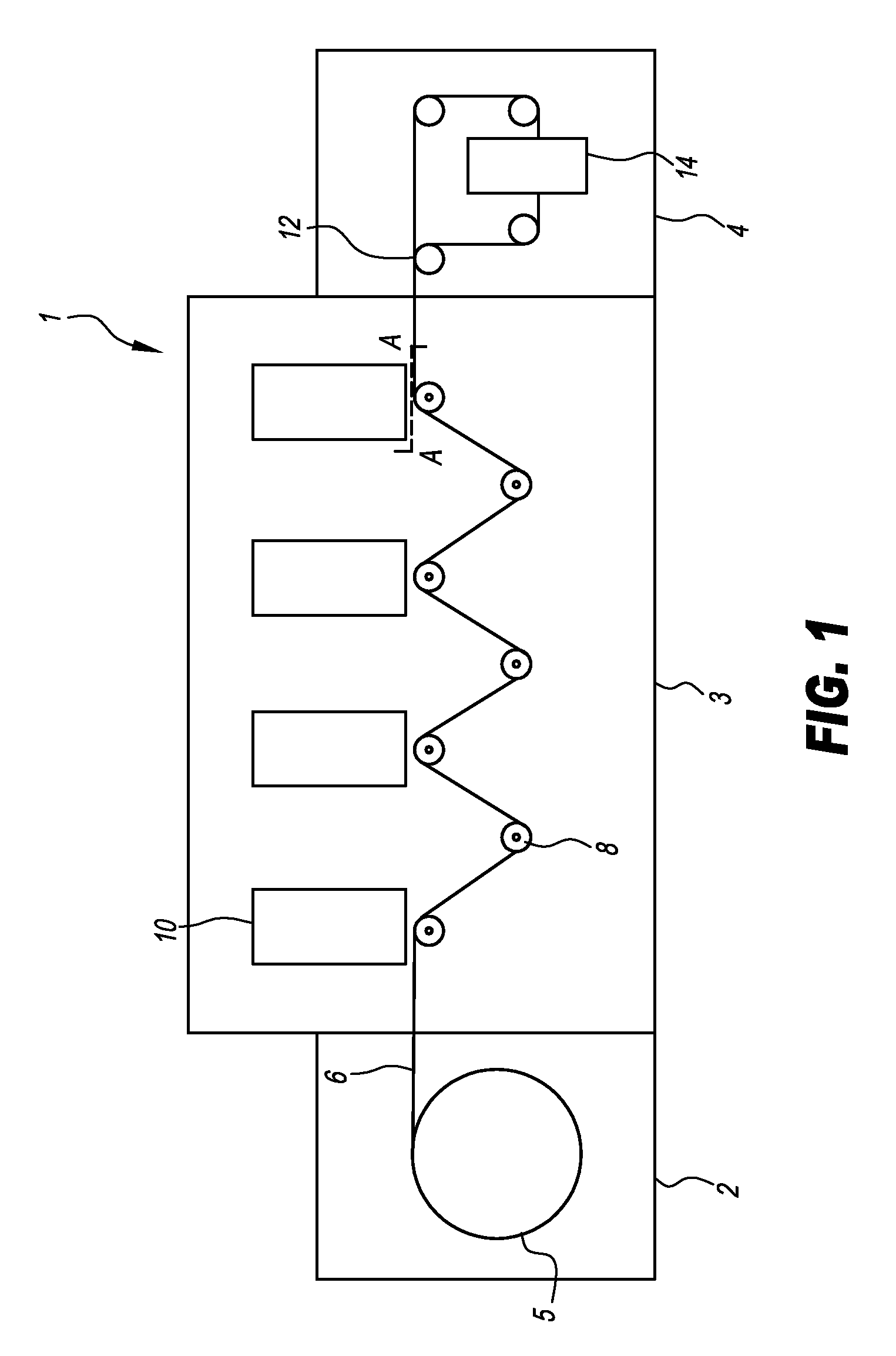
  • Device for turning sheet-like substrates
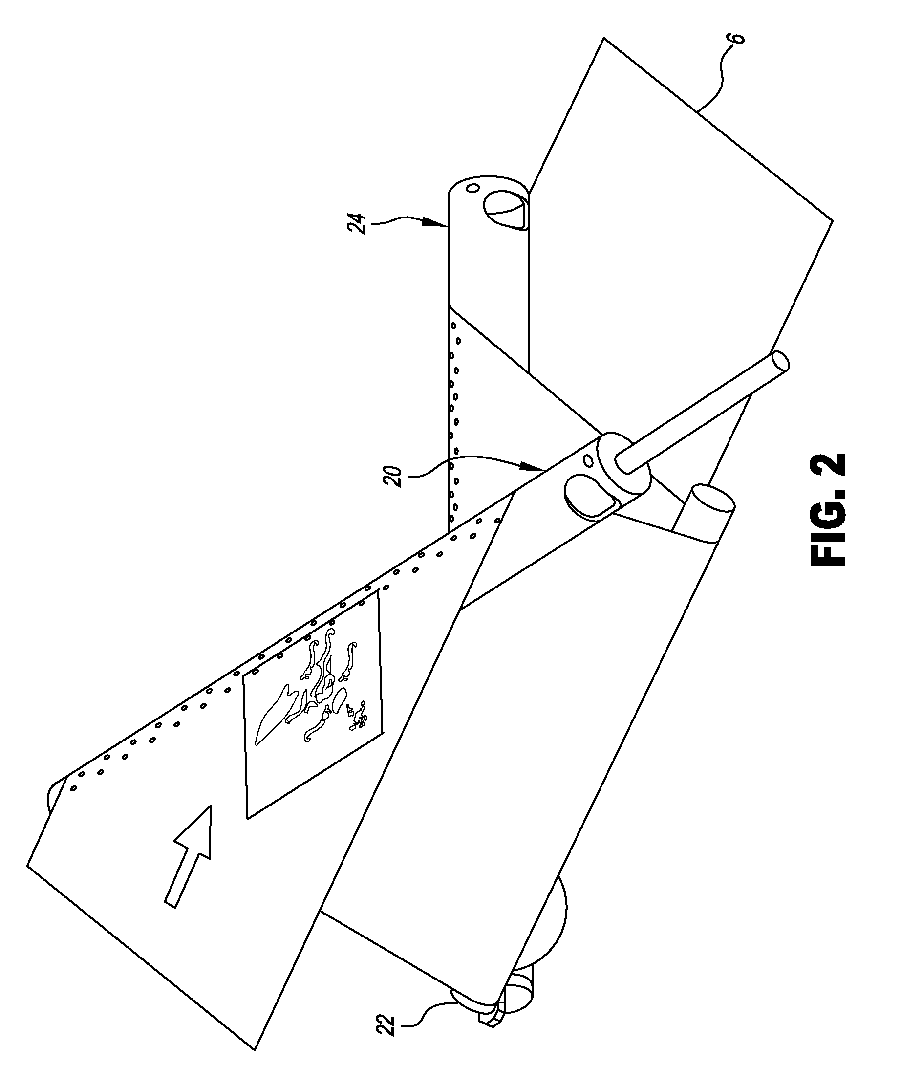
  • Device for turning sheet-like substrates

Examples


first embodiment

[0044]FIG. 6 shows a schematic detailed view of a continuous channel structure 60 in a substrate guide surface 30 of a turning element 20 in accordance with a The channel structure 60 can be designed in the form shown both in the area 32 in accordance with FIG. 4 and in the areas 45 of FIG. 5.

[0045]The channel structure 60 has a plurality of parallel-extending circumferential channels 62 and a transverse channel 64 provided in the substrate guide surface 30. The circumferential channels 62 extend in the circumferential direction of the turning element 20. The respective circumferential channels 62 are connected to one another via the transverse channel 64, the latter centrally intersecting the circumferential channels 62 in the circumferential direction of the turning element. It would of course also be possible to provide several transverse channels intersecting the circumferential channels 62 in the circumferential direction of the turning element at different points.

[0046]The ci...

second embodiment

[0050]FIG. 8 shows a schematic detailed view of an alternative continuous channel structure 100 in a substrate guide surface 30 of a turning element 20 in accordance with a The channel structure 100 can be designed in the form shown both in the area 32 in accordance with FIG. 4 and in the areas 45 of FIG. 5.

[0051]FIG. 8 shows a statistical distribution of one or more channels of the channel structure 100, with the following relating to only one channel. The channel is continuous, i.e. designed such that every point inside the channel is connected via the channel to any other point in the channel.

[0052]The distribution of the channel forming the channel structure 100 inside the substrate guide surface corresponds to a statistical distribution. The distribution of the channel structure 100 substantially follows a uniform distribution, but can have any required distribution. The channel forming the channel structure 100 has a depth of preferably 0.1 to 1 mm.

[0053]Gas outlet openings 6...


PUM


Abstract

A turning unit for sheet-like substrates has at least one first turning element with a basic body having an outer, round substrate contact surface for deflecting the substrate. The deflection is from a first sheet conveying direction to a second sheet conveying direction describing a predetermined angle to the first sheet conveying direction. Furthermore, a channel structure is provided that is formed in the substrate contact surface and onto which open a plurality of gas outlet openings which are in fluid communication with a gas supply.

Description

TECHNICAL FIELD OF THE INVENTION[0001]The present invention relates to a device for turning sheet-like substrates, in particular sheet-like substrates in a printing press, that are to undergo verso printing following recto printing.BACKGROUND OF THE INVENTION[0002]In printing technology, turning units are known which following recto printing use deflecting elements to turn sheet-like print materials for verso printing. A turning unit of this type is described for example in DE 43 35 473. The turning unit described there has two fixed turning elements rotated 90° to one another and a deflecting element positioned in a sheet running direction between the turning elements. The turning elements are each inclined 45° to a running direction of a substrate sheet, as a result of which they each provide a 90° turn.[0003]The turning elements can guide the substrate sheet in a sliding and contacting manner, or, as described in DE 43 35 473, over an air cushion between the substrate sheet and t...

Claims


Application Information

Patent Timeline
Patent Type & Authority Applications(United States)
IPC IPC(8): B65H23/24B65H23/32
CPCB65H23/24B65H23/32B65H2404/13161B65H2406/42B65H2406/111B65H2406/14B65H2404/1363B41J3/60
Inventor GRAVE, ERWINGOLDBECK, UWE
Owner EASTMAN KODAK CO
Learn More