Atomizing nozzle for fine spray and misting applications

a technology of fine spray and misting, which is applied in the direction of air humidification system, heating type, lighting and heating apparatus, etc., can solve the problems of high cost, difficult to provide a limited or controlled droplet size distribution, and high air consumption, so as to reduce the amount of air consumption, reduce the cost, and reduce the effect of air consumption

Inactive Publication Date: 2005-05-31
NAT RES COUNCIL OF CANADA
View PDF8 Cites 15 Cited by
  • Summary
  • Abstract
  • Description
  • Claims
  • Application Information

AI Technical Summary

Benefits of technology

[0012]The atomizer or nozzle of this invention achieves a narrow and controlled droplet size distribution with low air consumption and fine atomization without dripping. The reduction of air consumption is very advantageous in some applications where limits are placed on the size of compressor that can be used in the installation.

Problems solved by technology

The existing nozzles suffer from a number of shortcomings, such as high air consumption, the collection of large droplets on external components of the assembly, relatively high cost, difficulty in providing a limited or controlled droplet size distribution, and high noise levels due to high air consumption.
Many current nozzle designs are configured Dr optimized for only one flow condition or the operating range is very limited for achieving consistent, unchanged droplet size.
Also, many of the present designs that use air atomization are designed with one or more impactor plates that produce fine spray (typically less that 50 μm mean size) but the mounting for each plate interferes with the spray and often results in a fraction of the spray comprising course droplets resulting from an accumulation of liquid on the impactor-mounting components.
Another problem associated with prior art nozzles, as indicated above, is the noise level produced by the nozzles since they are used in commercial building air conditioning.

Method used


Image

  • Atomizing nozzle for fine spray and misting applications
  • Atomizing nozzle for fine spray and misting applications
  • Atomizing nozzle for fine spray and misting applications

Examples


Embodiment Construction

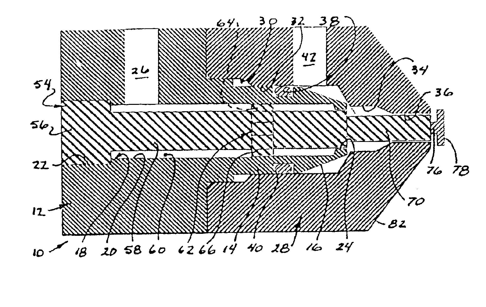
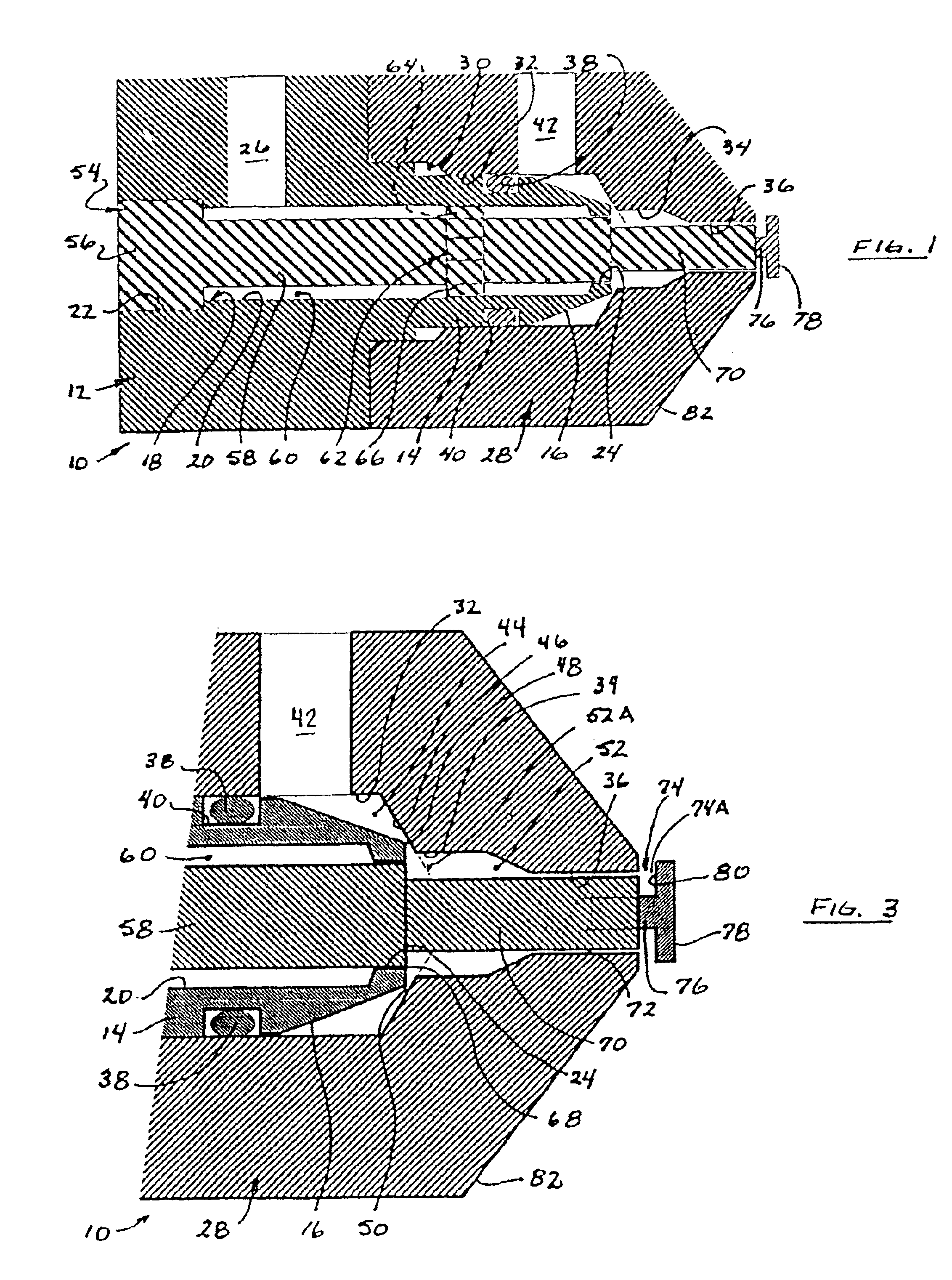
[0019]The present invention provides a nozzle 10 which includes a main nozzle body 12, which body may be of any suitable external cross-section, such as cylindrical, rectangular, or square, for example, depending on the particular application in which it will be used. The main body has a rearmost block portion and is stepped down at the forward end to create a cylindrical projection 14 that has a frustoconical end surface 16. A central bore 18 extends through the main body, the bore being stepped as well so as to define a main central section 20, a proximal section 22 of a diameter greater than that of the central section, and a short distal section 24 of a diameter smaller than that of the central section. The distal section 24 and a portion of the central section 20 reside within the projection 14. A radially directed inlet port or bore 26 extending through the main body communicates the bore 18 at the central section 20 with a source of pressurized air (not shown).

[0020]The main ...


PUM


Abstract

The invention relates to a nozzle (10) for mixing a gaseous fluid such as air and a liquid such as water and for ejecting an atomized mist of liquid droplets. The nozzle includes a nozzle body defining first (60), second (44) and third (52) annular passages along the length thereof. Pressurized fluid is introduced into the first annular passage (60) and a first restricted annular orifice (68) leads from the first annular passage (60) to the third annular passage (52). Liquid is introduced into the second annular passage (44) and a second restricted annular orifice (48) leads from the second annular passage (44) to the third annular passage (52). Liquid and gaseous fluid are aggressively mixed in the third annular passage (52). A third restricted annular orifice (72) leads from the third annular passage (52) to atmosphere such that mixed liquid and gaseous fluid are forcibly ejected from the nozzle through the third restricted annular orifice (72), the liquid being atomized in small controlled droplets in the ejected gaseous fluid.

Description

[0001]This application claims the benefit of Provisional Application Ser No. 60 / 168,770 filed Dec. 6, 1999.[0002]The present invention relates to a nozzle device for atomizing liquid for fine spray and misting applications. In particular the invention relates to a nozzle meeting criteria for air humidification in ducts used commercially in Heating Ventilating and Air Conditioning (HVAC) systems as well as in other humidification applications including localized spatial humidification for process and printing plant operations and greenhouse humidification.BACKGROUND OF THE INVENTION[0003]There are existing atomizer designs for the applications described above, the designs typically providing a spray that is dynamically controlled to vary air humidity level. Usually an array of nozzles is mounted within a duct or other area and the required humidification supply is varied by adjusting air and water pressures to suit the desired bulk vaporization rate. The existing nozzles suffer from ...

Claims


Application Information

Patent Timeline
Patent Type & Authority Patents(United States)
IPC IPC(8): B05B7/04B05B1/26F24F6/12F24F6/14
CPCB05B1/265B05B7/0433F24F6/14Y02B30/545F24F2006/143Y02B30/54
Inventor MCCRACKEN, THOMAS W.BENNETT, ADAM J.DIGNARD, RONALD J. R.POULIN, CHARLES
Owner NAT RES COUNCIL OF CANADA
Why Eureka
Try Eureka