Direct drive wind turbine

a direct drive, wind turbine technology, applied in the direction of electric generator control, machines/engines, mechanical equipment, etc., can solve the problems of time-consuming and difficult maintenance, and achieve the effect of facilitating maintenance and compensating dynamic effects, and high-repeativity rotation

Active Publication Date: 2013-01-24
SIEMENS GAMESA RENEWABLE ENERGY AS
View PDF4 Cites 9 Cited by
  • Summary
  • Abstract
  • Description
  • Claims
  • Application Information

AI Technical Summary

Benefits of technology

[0023]The static element of the rotation sensor may comprise a Hall-effect sensor and/or an optical sensor. The Hall-effect sensor and/or the optical sensor may be adapted to detect the indentations, slots, holes, grooves and the like on the static element. The Hall-effect sensor may be adapted to detect the protrusions, slots, holes, grooves and the like of the first scale on the static element of the rotation sensor, whereas the optical sensor may be configured to detect the indentations, slots, holes, grooves and the like of the second scale of the static element of the rotation sensor. There

Problems solved by technology

Because the rotation sensor is large and is suspended in the cavity of the stator, access to components such as the hub is partially blocked, so that maintenance is made more difficult and

Method used


Image

  • Direct drive wind turbine
  • Direct drive wind turbine
  • Direct drive wind turbine

Examples


first embodiment

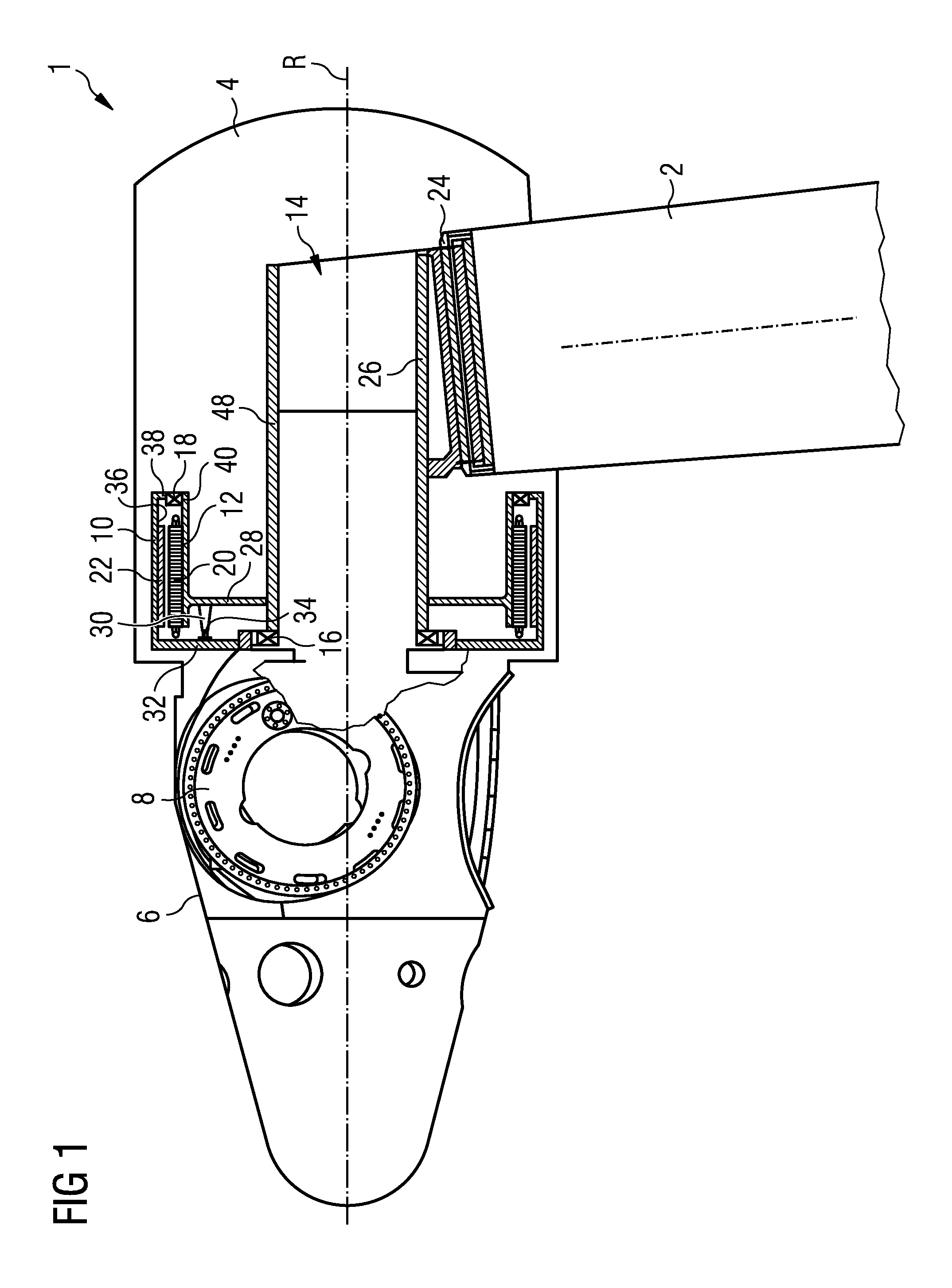
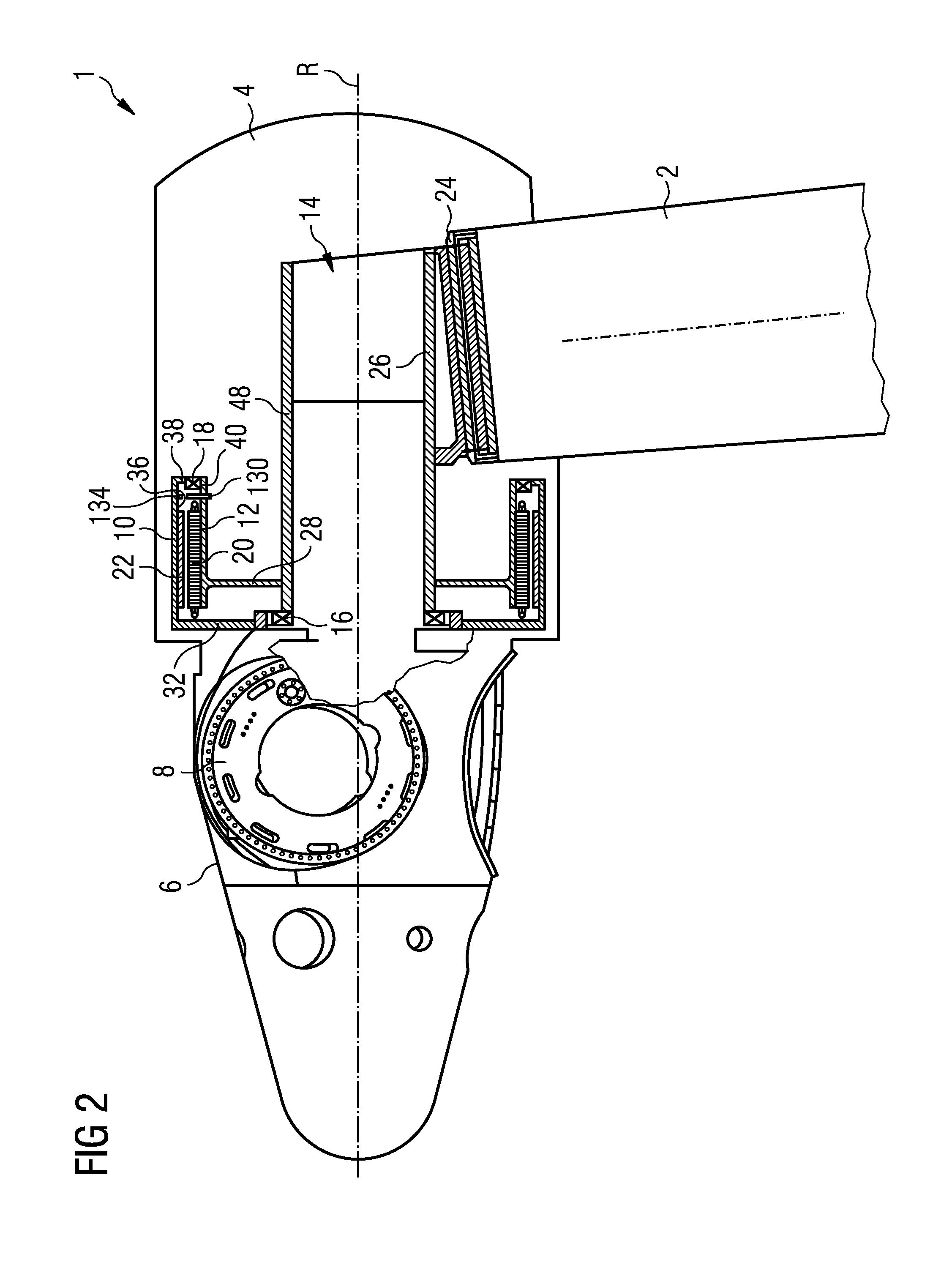
[0040]The first embodiment is shown in FIG. 1. The static element 30 of the rotation sensor is arranged on the stator support 28 arranged on a stator cavity wall 48 of the stator cavity. The movable element 34 of the sensor is arranged on the front rotor flange 32 supported by the main bearing 16. The movable element 34 is radially spaced apart from the axis of rotation R of the hub 6. Therefore, the movable element 34 comprises a large circumference and thus provides a comparable high resolution. The larger the radial distance of the movable element 34 of the rotation sensor from the rotation axis R, the higher the resolution of the rotation sensor. Although the movable element 34 of the rotation sensor is spaced apart from the rotational axis R for a comparably high value, the movable element 34 of the rotation sensor is still located close the main bearing 16.

[0041]As mentioned before, the main bearing 16 supports the rotor 10 and particularly the front rotor flange 32. According...

third embodiment

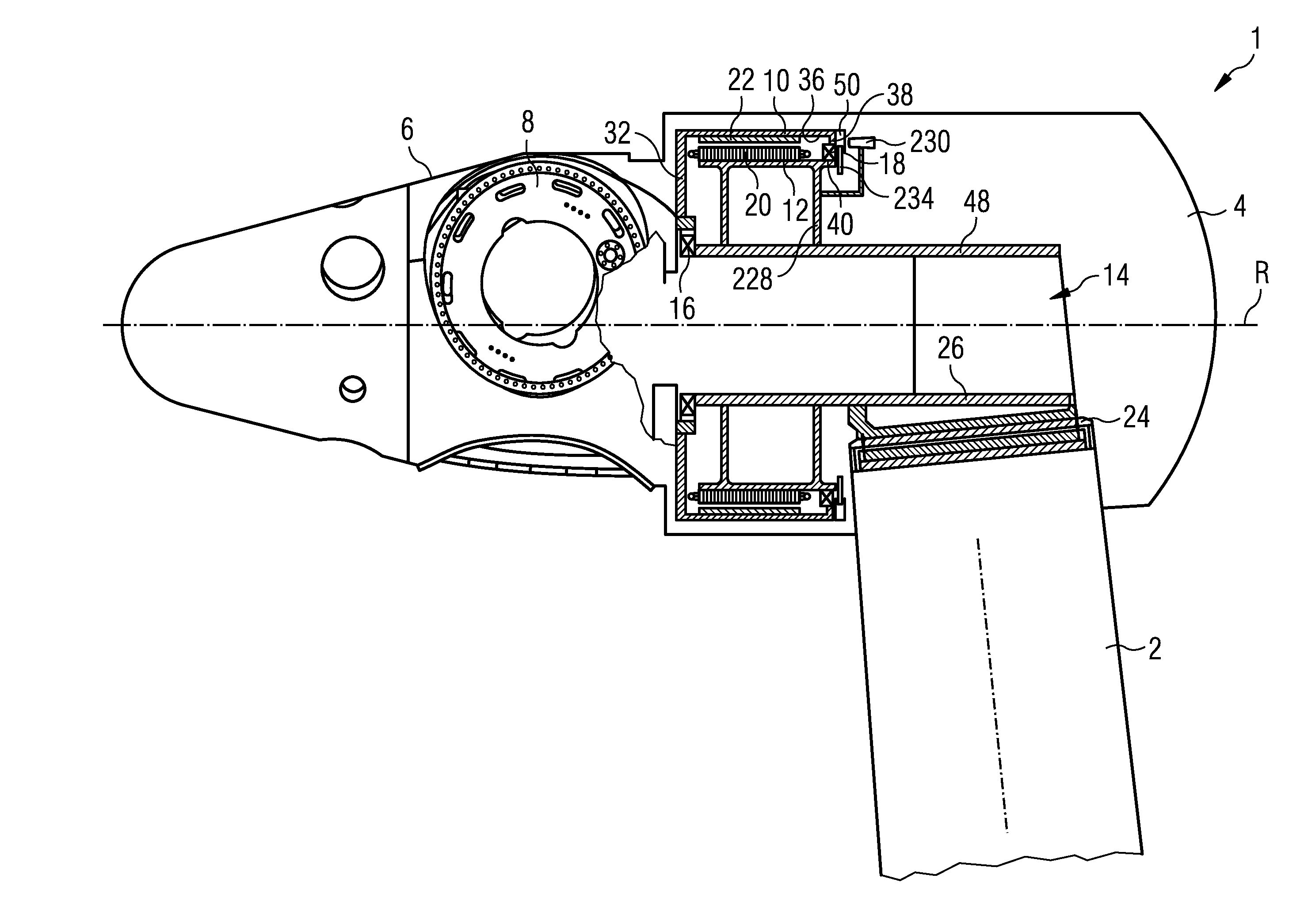
[0043]Reference is made to FIG. 3 showing the direct drive wind turbine having the inventive rotation sensor. A brake disc 40 or brake flange 40 may be mounted on the rear rotor flange 38. The movable element 234 may be mounted next to the brake disc 40 or on the rear rotor flange 38. The fixed element 230 of the rotation sensor may be connected to a rear stator support 228. In this embodiment, both the static element 230 and the moving element 234 of the rotation sensor are accessible by maintenance staff. Neither the static element 230 nor the moving element 234 is covered by any part of the rotor 10 or stator 12. The moving element 234 of the rotation sensor can be incorporated in the rotor rear flange 38.

[0044]Since the movable element 234 of the rotation sensor is located near the secondary bearing 18, which only provides radial support, the movable element 234 may be subject to axial play and deviation from the axial position. Thus, the static sensor element 230 must have a de...

fourth embodiment

[0045]FIG. 4 shows the direct drive wind turbine having the inventive rotation sensor. In the embodiment of FIG. 3 the scale of the movable element 234 has to be detected in the axial direction. In the embodiment of FIG. 4 the scale of the movable element 334 has to be detected in the radial direction. As with the embodiment according to FIG. 3 the movable element 334 of the rotation sensor is arranged on the rear rotor flange 38. The brake disc 50 may be provided on the rear rotor flange 38. The static element 330 of the rotation sensor may be provided on a rear stator support 328. The movable element 334 of the rotation sensor is located close to a secondary bearing 18 only providing support in the radial direction. Accordingly, the scale of the movable element 334 may have a play in the axial direction. However, such play or position tolerance of the movable element 334 does not change the distance between the static sensor element 330 comprising a detection unit such as a Hall-e...


PUM


Abstract

Disclosed is a direct drive wind turbine including a plurality of blades connected to a hub, a generator including a stator and a rotor, the stator being fixed on a nacelle of the wind turbine and a rotation sensor having a static element and a moving element. The hub is directly connected to the rotor of the generator. The static element of the rotation sensor is mounted on a stationary element of the wind turbine, in particular the stator, at a distance from the rotation axis of the hub, and the moving element of the rotation sensor is mounted on the rotor of the generator at a distance from the rotation axis of the hub.

Description

CROSS REFERENCE TO RELATED APPLICATIONS[0001]This application is the US National Stage of International Application No. PCT / EP2010 / 070303, filed Dec. 20, 2010 and claims the benefit thereof. The International Application claims the benefits of European application No. 10157903.5 filed Mar. 26, 2010. All of the applications are incorporated by reference herein in their entirety.FIELD OF INVENTION[0002]The invention relates to a direct drive wind turbine, comprising a plurality of blades connected to a hub, a generator comprising a stator and a rotor, whereby the stator is fixed on a nacelle of the wind turbine and the hub is directly connected to the rotor, and a rotation sensor having a static element and a moving element.BACKGROUND OF INVENTION[0003]The wind turbine comprises a tower on which a nacelle is mounted by a yaw turning system. The nacelle supports a hub to which the blades are connected. In a conventional wind turbine the hub turns a main shaft which in turn drives a gea...

Claims


Application Information

Patent Timeline
IPC IPC(8): F03D9/00
CPCF03D1/065F03D7/0224F05B2220/7066F05B2270/326F05B2270/809H02K7/1838F03D11/00H02K11/0021H02K11/0026H02K2213/06Y02E10/721Y02E10/723Y02E10/725H02K11/0015H02K11/21H02K11/215H02K11/22F03D80/00F03D80/70Y02E10/72
Inventor THOMSEN, THYGE SKOVBJERG
Owner SIEMENS GAMESA RENEWABLE ENERGY AS
Why Eureka
Try Eureka