Light bar structure and light source device

Active Publication Date: 2013-01-24
WISTRON CORP
View PDF23 Cites 9 Cited by
  • Summary
  • Abstract
  • Description
  • Claims
  • Application Information

AI Technical Summary

Benefits of technology

[0017]The present invention does not utilize the conventional surface mount technology to fix the light unit on the light bar structure. The light bar structure and the light source device of the present invention has advantages of simple structure, easy assembly, low material cost and manuf

Problems solved by technology

Material cost and manufacturing cost of the aluminum base is expensive and has great heat dissipating efficiency, so that the aluminum base is usually applied for high power light emitting diode, such as panel with large dimensions or huge monitor.
However, the light emitting diode has to be fixed on the al

Method used


Image

  • Light bar structure and light source device
  • Light bar structure and light source device
  • Light bar structure and light source device

Examples


Embodiment Construction

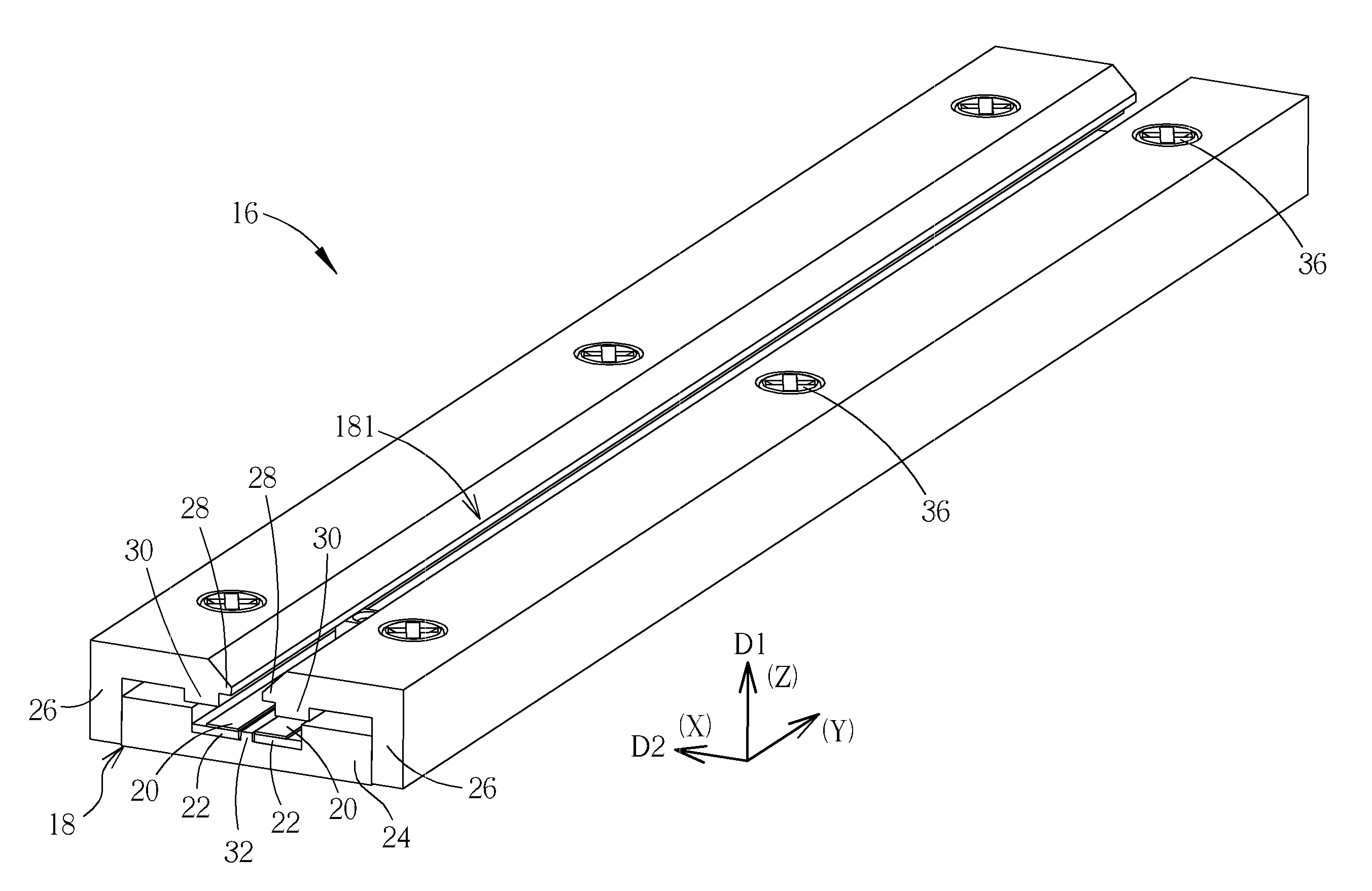
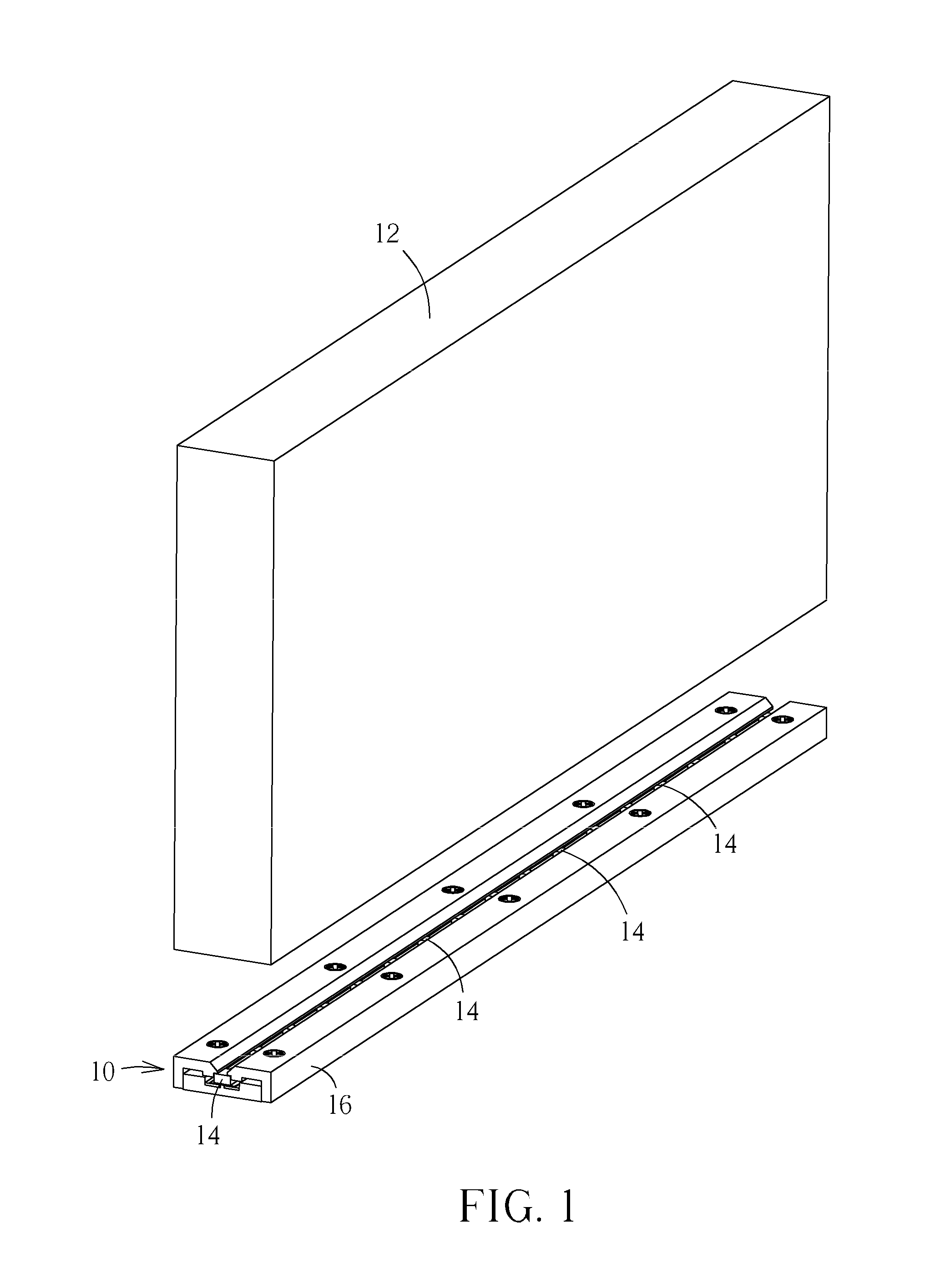
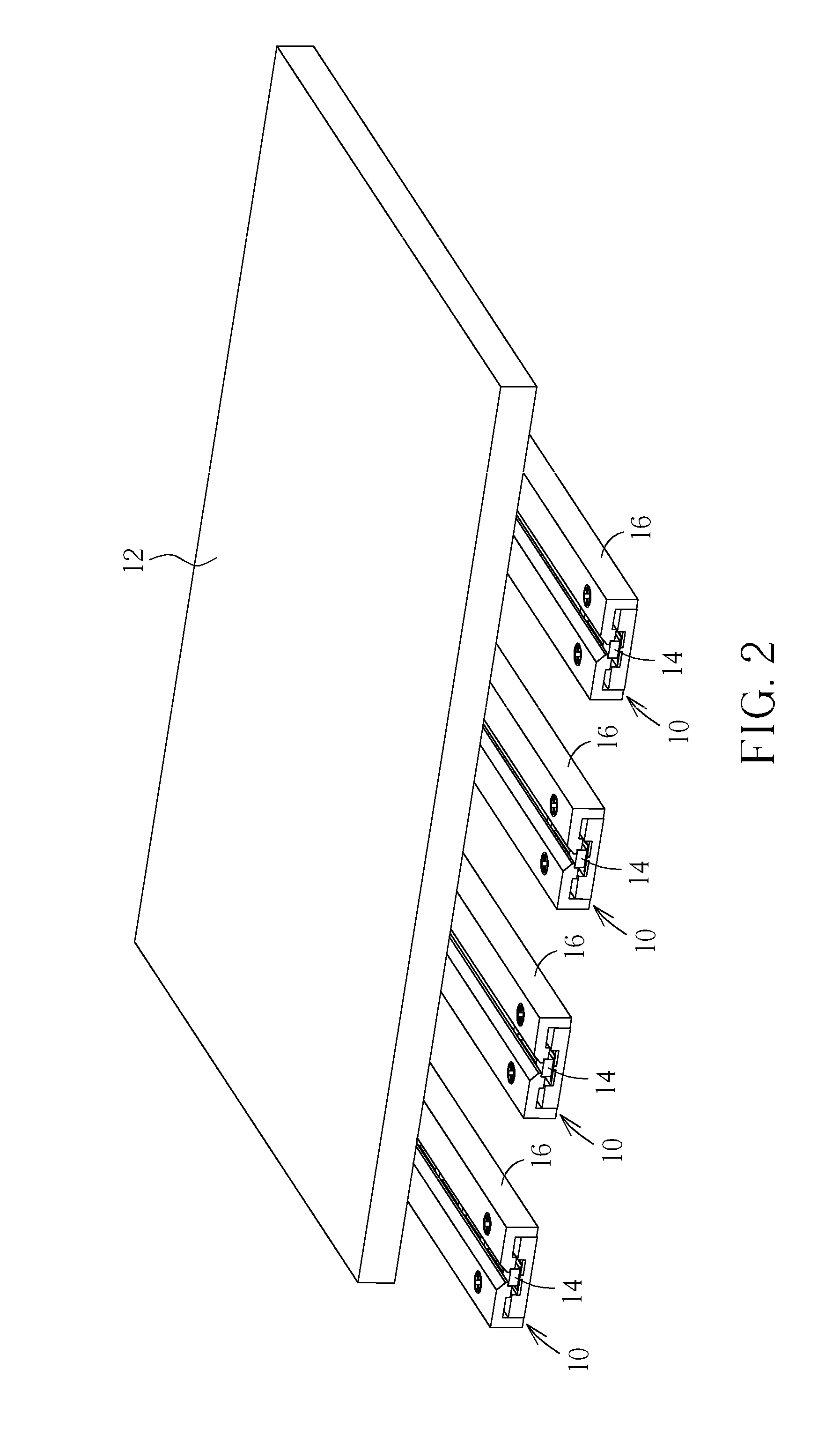
[0024]Please refer to FIG. 1 and FIG. 2. FIG. 1 and FIG. 2 are diagrams of a light source device 10 in different applications according to an embodiment of the present invention. The light source device 10 can be assembled with a corresponding optical plate 12 according to design demand for applying on a liquid crystal panel or a liquid crystal display. As shown in FIG. 1, the light source device 10 can be disposed by a side of the optical plate 12 (such as a light guiding plate) for forming a side-in backlight module. As shown in FIG. 2, the light source devices 10 can be arranged under the optical plate 12 (such as a diffusion plate) for forming a direct-type backlight module. The light source device 10 includes a plurality of light units 14 and a light bar structure 16. The light unit 14 can be a light emitting diode, and the light bar structure 16 is for fixing the plurality of LEDs, so as to transmit beams generated from the plurality of LEDs to the optical plate 12 for forming...


PUM


Abstract

A light bar structure is disclosed in the present invention. The light bar structure includes a housing whereinside an accommodating space is formed, and the accommodating space is for accommodating a light unit. The housing includes an engaging portion for engaging with the light unit to constrain a movement of the light unit at a first direction, and a contacting portion for contacting against the light unit to constrain a movement of the light unit at a second direction different from the first direction. The light bar structure further includes an isolating component disposed on a bottom inside the housing, and two conductive components disposed on the isolating component for electrically connecting two electrodes of the light unit.

Description

BACKGROUND OF THE INVENTION[0001]1. Field of the Invention[0002]The present invention relates to a light bar structure and a light source device, and more particularly, to a light bar structure and a light source device having low material cost and manufacturing cost without utilizing surface mount technology.[0003]2. Description of the Prior Art[0004]Surface mount technology (SMT) is utilized to fix the light emitting diode on the base in the conventional light bar structure. The conventional base can be made of aluminum material or copper material. Material cost and manufacturing cost of the aluminum base is expensive and has great heat dissipating efficiency, so that the aluminum base is usually applied for high power light emitting diode, such as panel with large dimensions or huge monitor. Cost of the copper base (FR4 plate) is cheaper than the aluminum base, and the copper base has normal heat dissipating efficiency, so the copper base is usually applied for low power light em...

Claims


Application Information

Patent Timeline
IPC IPC(8): F21V21/00
CPCF21S4/008F21Y2103/003F21Y2101/02F21S4/28F21Y2103/10F21Y2115/10F21S4/20F21V19/0045F21V19/0025F21V19/0035F21V21/34F21V21/35F21V21/025F21V21/005G02B6/0085F21V19/02
Inventor HSU, CHIH-HUAHSU, PIN-HUNGLIAU, JUNG-SHIUNG
Owner WISTRON CORP
Why Eureka
Try Eureka