Imaging and Eccentric Atherosclerotic Material Laser Remodeling and/or Ablation Catheter
a laser remodeling and atherosclerotic material technology, applied in the field of medical devices, systems and methods, can solve the problems of invasive bypass surgery, increased risk of major surgical complications, and limited blood flow,
- Summary
- Abstract
- Description
- Claims
- Application Information
AI Technical Summary
Benefits of technology
Problems solved by technology
Method used
Image
Examples
embodiment 110
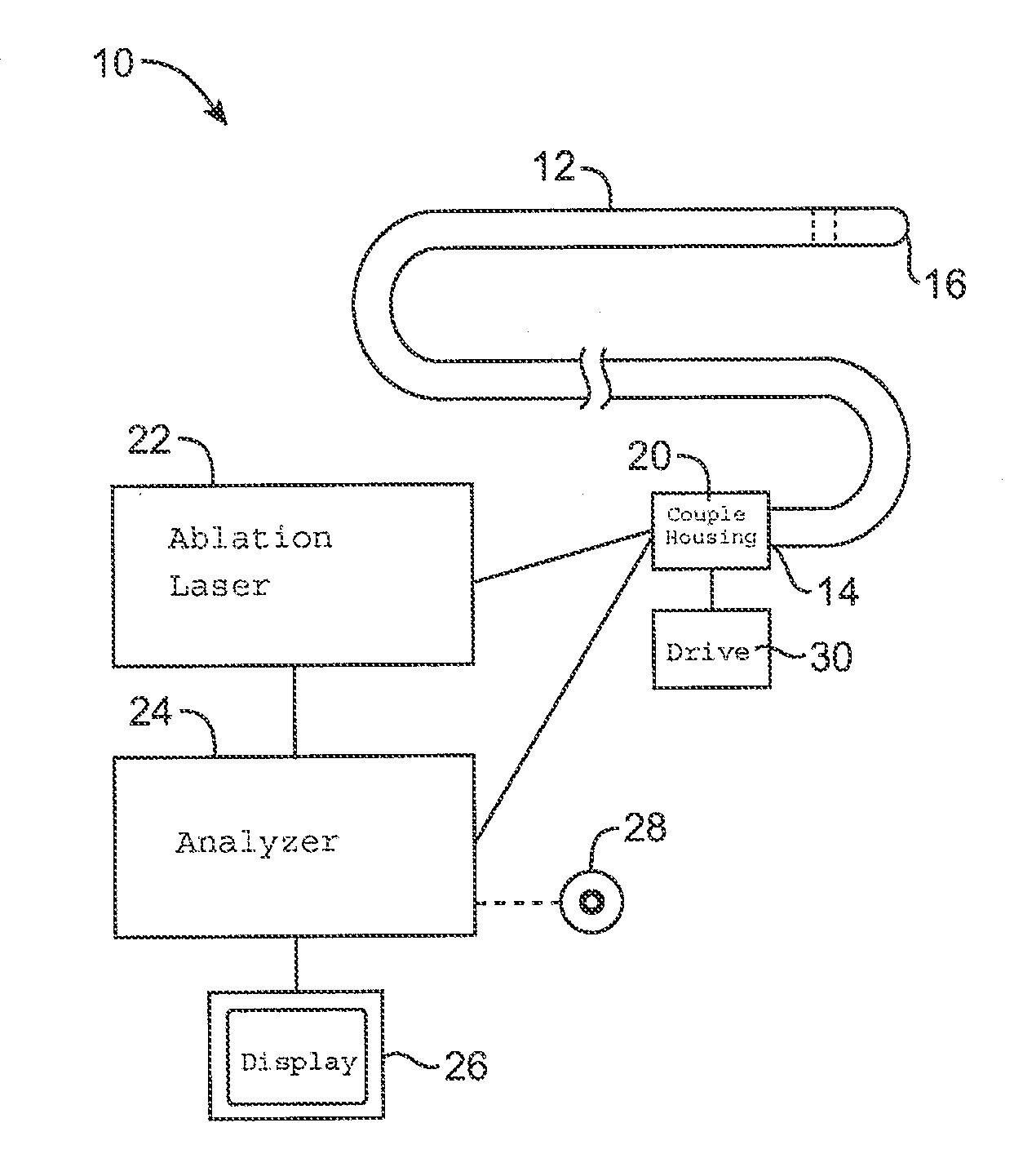
[0114]A preferred embodiment 110 can be understood with reference to FIG. 8. In this preferred embodiment, the same optical conduit or bundle of optical conduits 102 is used to convey the light energy for imaging, say imaging light 112, and the light energy for ablating atherosclerotic plaques, say remodeling and / or ablating light 114. The optical conduits are housed inside a sleeve catheter or guidewire 104.
[0115]As can be understood with reference to FIGS. 8, 9A-9D, and 10A-10D, the optical conduits rotate continuously inside the sleeve catheter. The imaging light runs through the optical conduits and radially through transparent cylindrical windows 122 to provide an intra-vascular image of artery 116, for instance by OCT. The image is processed by a computer that identifies and localizes atherosclerotic plaques 118. Based on the information from the imaging, the computer then determines when to fire the ablating light 114 such that the light ablates specifically the plaque and do...
embodiment 120
[0116]A preferred embodiment 120 can be understood with reference to FIG. 11. Two different optical conduits or bundles of optical conduits, 102a and 102b, are used to convey the light energy for imaging, say imaging light 112, and the light energy for ablating and / or remodeling atherosclerotic plaques, say ablating light 114. The optical conduits are housed inside a sleeve catheter 104 or guidewire. As shown in FIG. 12, conduits 102a, 102b can rotate around a common longitudinal axis 124. The fold mirrors 108 are facing first and second radial directions, often being opposed directions.
[0117]Optical conduits 102a and 102b may rotate continuously inside sleeve catheter 104. The imaging light runs through optical conduit 102a and provides an intra-vascular image of the artery, for instance by OCT. The ablating light runs through conduit 102b. The imaging and ablating lights can be used sequentially or simultaneously. The image is processed by a computer that identifies and localizes ...
embodiment 130
[0118]Preferred embodiment 130 may be understood with reference to FIGS. 13-16F. Two different optical conduits or bundles of optical conduits 102a and 102b, are used to convey the light energy for imaging, say imaging light 112, and the light energy for remodeling and / or ablating atherosclerotic plaques, say ablating light 114. The optical conduits 102a, 102b are housed inside a sleeve catheter or guidewire. Conduits 102a and 102b again may rotate around a common longitudinal axis, with their associated lenses 106 and fold mirrors 108 may be being axially staggered or separated and their optical paths facing either the same or different directions, depending on the configuration. The illustration of FIGS. 14A-14D and 15A-15D show the optical paths facing the same direction, and the imaging light 112 and the ablating light 114 being used sequentially. The illustration of FIG. 16 shows a different configuration: the imaging and optical paths face different, generally opposed directio...
PUM
 Abstract
Description
Claims
Application Information
 - R&D
- Intellectual Property
- Life Sciences
- Materials
- Tech Scout
- Unparalleled Data Quality
- Higher Quality Content
- 60% Fewer Hallucinations
Browse by: Latest US Patents, China's latest patents, Technical Efficacy Thesaurus, Application Domain, Technology Topic, Popular Technical Reports.
© 2025 PatSnap. All rights reserved.Legal|Privacy policy|Modern Slavery Act Transparency Statement|Sitemap|About US| Contact US: help@patsnap.com


