
N-channel and p-channel finfet cell architecture

a cell architecture and finfet technology, applied in the field of integrated circuit devices, cell libraries, cell architectures and electronic design automation tools for, can solve the problems of increasing the requirements of compact layout and low power

Active Publication Date: 2013-01-31
SYNOPSYS INC
View PDF2 Cites 132 Cited by
  • Summary
  • Abstract
  • Description
  • Claims
  • Application Information

AI Technical Summary

Benefits of technology

This patent describes the use of finFET block structures to create highly customizable cells for integrated circuit design. The technology allows for the creation of finFET standard cell libraries that can be used in electronic design automation software and systems. The use of finFET blocks can improve the performance and efficiency of integrated circuits. Overall, this patent provides a way to make complex integrated circuits more efficiently and easily.

Problems solved by technology

FinFETs have gained acceptance recently as the requirements of low power and compact layout have become more demanding.

Method used


Image

  • N-channel and p-channel finfet cell architecture
  • N-channel and p-channel finfet cell architecture
  • N-channel and p-channel finfet cell architecture

Examples


Embodiment Construction

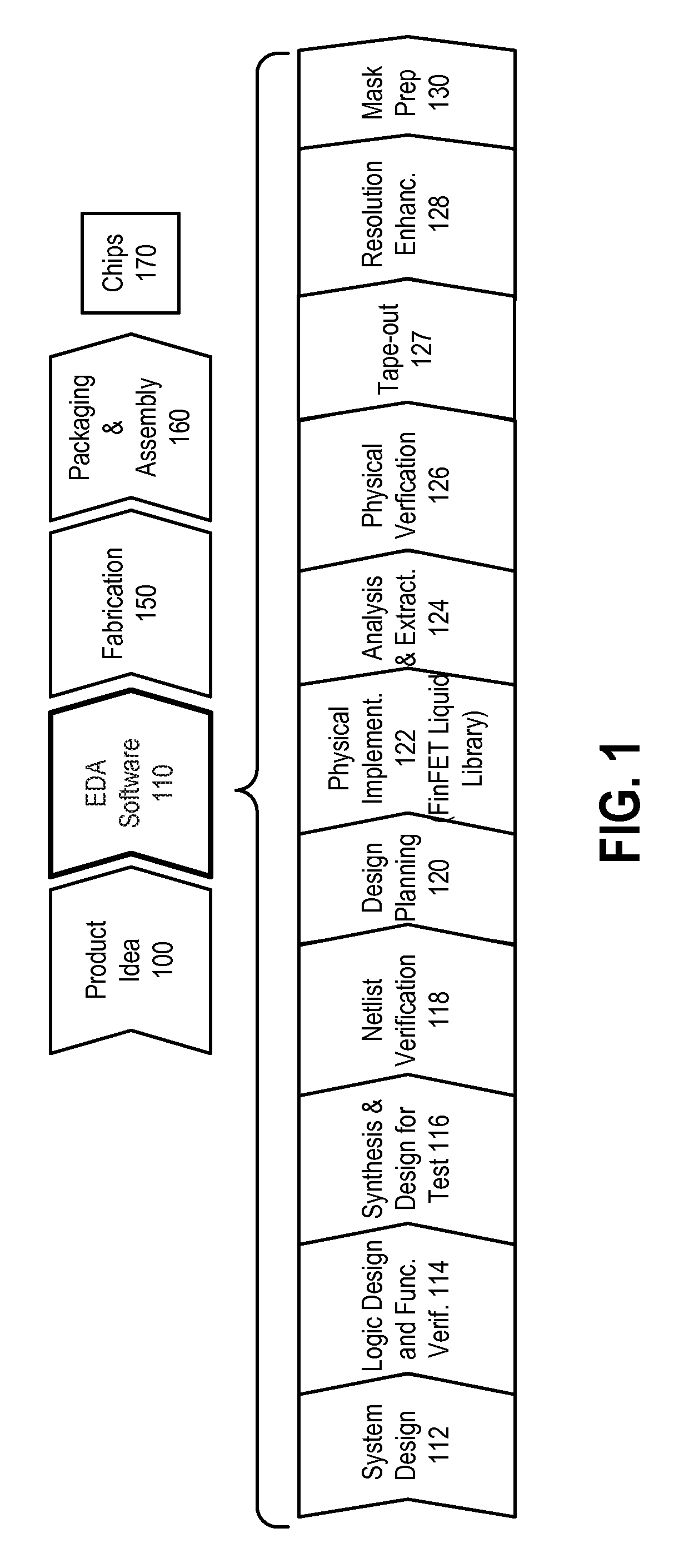
[0019]FIG. 1 is a simplified representation of an integrated circuit design flow. As with all flowcharts herein, it will be appreciated that many of the steps of FIG. 1 can be combined, performed in parallel or performed in a different sequence without affecting the functions achieved. In some cases a rearrangement of steps will achieve the same results only if certain other changes are made as well, and in other cases a rearrangement of steps will achieve the same results only if certain conditions are satisfied. Such rearrangement possibilities will be apparent to the reader.

[0020]At a high level, the process of FIG. 1 starts with the product idea (block 100) and is realized in an EDA (Electronic Design Automation) software design process (block 110). When the design is finalized, the fabrication process (block 150) and packaging and assembly processes (block 160) occur, ultimately resulting in finished integrated circuit chips (result 170).

[0021]The EDA software design process (b...


PUM


Abstract

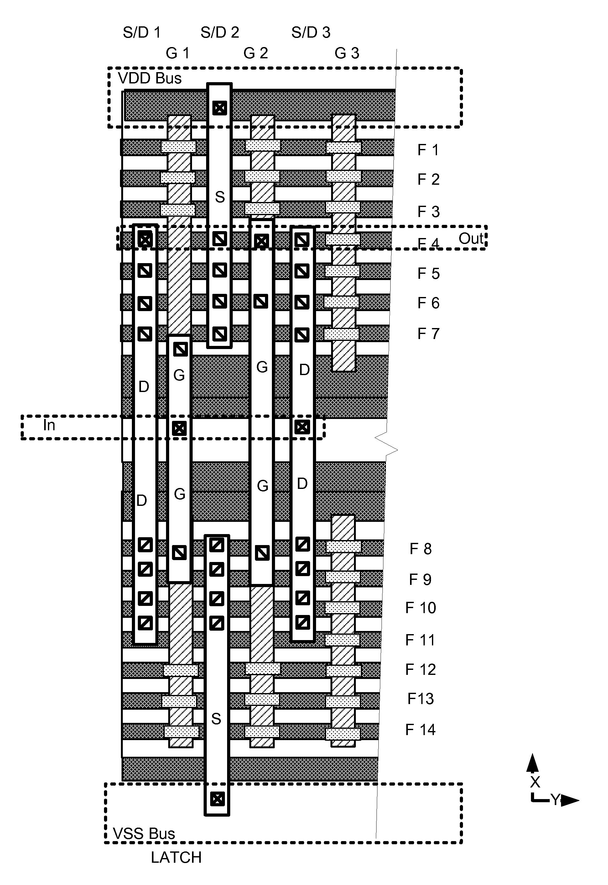
A finFET block architecture suitable for use of a standard cell library, is based on an arrangement including a first set of semiconductor fins in a first region of the substrate having a first conductivity type, and a second set of semiconductor fins in a second region of the substrate, the second region having a second conductivity type. A patterned gate conductor layer including gate traces in the first and second regions, arranged over channel regions of the first and second sets of semiconductor fins is used for transistor gates. Patterned conductor layers over the gate conductor layer are arranged in orthogonal layout patterns, and can include a plurality of floating power buses over the fins in the first and second regions.

Description

BACKGROUND[0001]1. Field of the Invention[0002]The present invention relates to integrated circuit devices, cell libraries, cell architectures and electronic design automation tools for integrated circuit devices, including finFET devices.[0003]2. Description of Related Art[0004]FinFET style transistors have been described in D. Hisamoto et al., IEDM, 1998; and N. Lindert et al., IEEE Electron Device Letters, p. 487, 2001. FinFETs have gained acceptance recently as the requirements of low power and compact layout have become more demanding.[0005]In the design of integrated circuits, standard cell libraries are often utilized. It is desirable to provide a finFET-based design architecture suitable for implementation of cells for a standard cell library, and for implementation of integrated circuits using finFET architectures with flexible layout features.SUMMARY[0006]FinFET block structures suitable for implementation of a wide variety of cells, and creation of finFET standard cell li...

Claims


Application Information

Patent Timeline
Patent Type & Authority Applications(United States)
IPC IPC(8): H01L27/12G06F17/50H01L21/82
CPCH01L29/66795H01L29/785H10B10/12H10B10/18H01L27/0207H01L27/1211H01L2924/0002H01L27/0924G06F30/39H01L2924/00G06F30/30G06F30/392H01L27/0886H01L23/5286H01L23/535H01L29/0649H01L29/41791
Inventor KAWA, JAMILMOROZ, VICTORSHERLEKAR, DEEPAK
Owner SYNOPSYS INC
Learn More