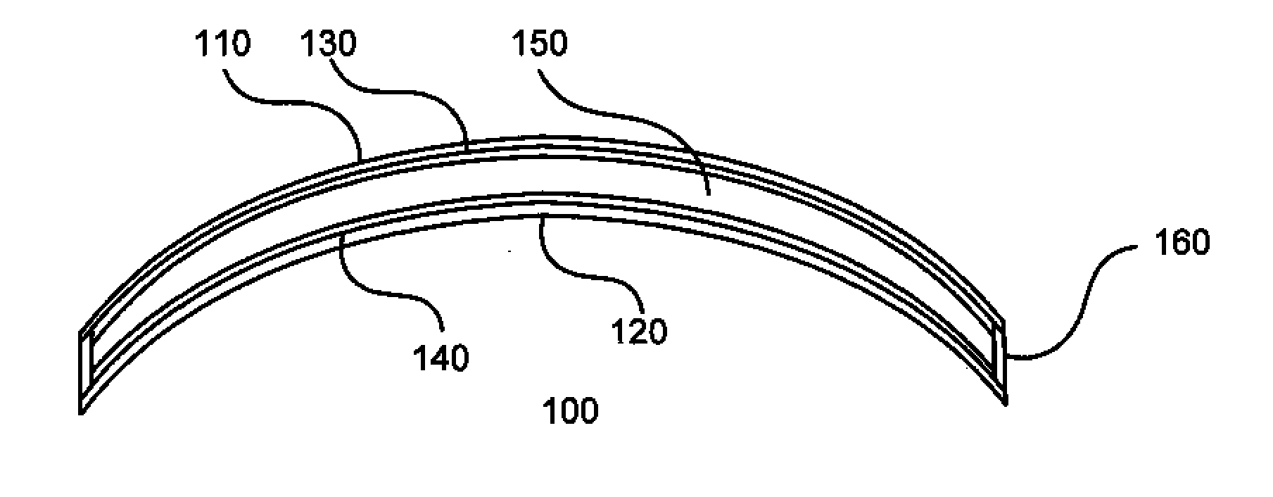
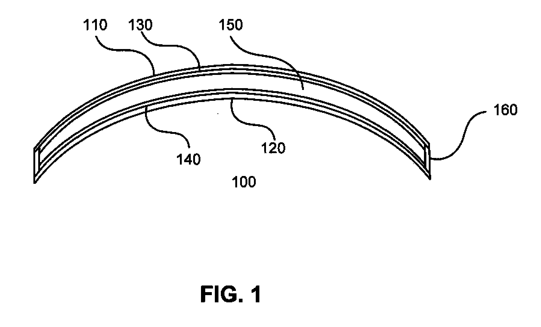
Electro-Active Lenses Including Thin Glass Substrates

a technology of electronic focusing and thin glass substrate, applied in the field of can solve the problems of high cost of goods, high cost of electronic lenses, and limited material selection for electronic focusing ophthalmic lenses today

Active Publication Date:
View PDF4 Cites 47 Cited by
  • Summary
  • Abstract
  • Description
  • Claims
  • Application Information

AI Technical Summary

Benefits of technology

[0010]The invention disclosed herein provides a simplified way of constructing an electronic focusing ophthalmic lens, which can be materially independent of the lens blank. One significant aspect of the invention is that the liquid crystal cell is self contained, can be stand alone, and is made independent of the semi-finished lens blank to which it is later attached or affixed.

Problems solved by technology

There are two major components that drives up the cost of goods of such electronic focusing eyeglasses and both pertain to the cost of the electronic lenses.
Because the diffractive region is located on the external front surface of the 1.67 back semifinished lens blank, the significant bulk of the material with the present electronic focusing lens is made from an expensive premium material.
And because the index of the liquid crystal must closely match that of the 1.67 back, the material selection which can be used to make today's commercially available electronic focusing ophthalmic lens is very much limited.
Other factors to consider include the fact that, while plastic lenses are light weight, they have tendency to scratch.
On the other hand, glass is highly scratch resistant but is heavy.
Glass-plastic composite lenses have been tried in the past but have tended to fail due to thermal expansion differences causing delamination of the glass from the plastic.

Method used


Image

  • Electro-Active Lenses Including Thin Glass Substrates
  • Electro-Active Lenses Including Thin Glass Substrates
  • Electro-Active Lenses Including Thin Glass Substrates

Examples


Embodiment Construction

[0043]It is understood that the invention is not limited to the particular methodology, protocols, and reagents, etc., described herein, as these may vary as the skilled artisan will recognize. It is also to be understood that the terminology used herein is used for the purpose of describing particular embodiments only, and is not intended to limit the scope of the invention. It also is be noted that as used herein and in the appended claims, the singular forms “a,”“an,” and “the” include the plural reference unless the context clearly dictates otherwise. Thus, for example, a reference to “a layer” is a reference to one or more layers and equivalents thereof known to those skilled in the art.

[0044]Unless defined otherwise, all technical and scientific terms used herein have the same meanings as commonly understood by one of ordinary skill in the art to which the invention pertains. The embodiments of the invention and the various features and advantageous details thereof are explain...


PUM

PropertyMeasurementUnit
thicknessaaaaaaaaaa
thicknessaaaaaaaaaa
thicknessaaaaaaaaaa

Abstract

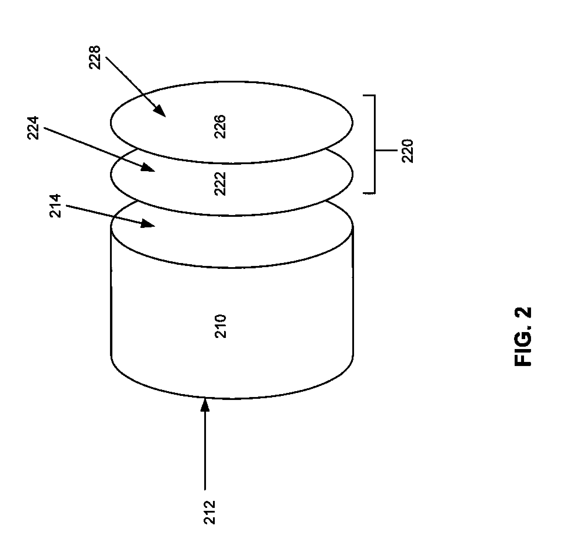
An electro-active optical cell is described including a layer of electro-active material, a front glass substrate member, and a back glass substrate member. The optical cell is capable of independently providing changeable optical power with the application of an electrical potential. The cell is also configured to be affixed to an external surface of a plastic substrate and to provide the changeable optical power, with at least one of the front substrate or the back substrate of the optical cell being an outermost optical layer. The layer of electro-active material may have a thickness less than 10 μm, and the glass substrate members may each have a thickness approximately between 20 μm and 500 μm.

Description

CROSS-REFERENCES TO RELATED APPLICATIONS[0001]This application claims the benefit of U.S. Ser. No. 61 / 492,433 filed on Jun. 2, 2011; U.S. Ser. No. 61 / 494,637 filed on Jun. 8, 2011; and U.S. Ser. No. 61 / 513,708 filed on Aug. 1, 2011, the contents of which are incorporated by reference in their entireties.BACKGROUND OF THE INVENTION[0002]The present invention relates to electro-active lenses, which may include, for example, ophthalmic lenses such as spectacle lenses, and / or non-ophthalmic lenses, such as a camera lens, etc. More specifically, the present invention relates electro-active cells including one or more thin glass layers, as well as to lenses which may include such cells.[0003]Electronic lenses and electronic focusing eyeglasses are known and now commercially available. U.S. Pat. Nos. 6,619,799; 7,290,875; 6,626,532; and 7,009,757 (the contents of which are hereby incorporated by reference herein for all purposes) are presented as selective examples of electronic focusing o...

Claims


Application Information

Patent Timeline
Patent Type & Authority Applications(United States)
IPC IPC(8): G02F1/29G02F1/133
CPCG02C7/083
Inventor BLUM, RONALDGUPTA, AMITAVAKOKONASKI, WILLIAMIYER, VENKATRAMANI
Why Eureka
Try Eureka