Method and Apparatus for Laminating Composites

a composite and laminating technology, applied in the direction of process and machine control, mechanical control devices, instruments, etc., can solve the problems of inefficiency in laying down relatively short non-zero tape courses, narrow structures, and inconvenient laminating of composites, so as to improve wrinkle absorption measures, reduce waste, and improve the effect of width dimensions

Active Publication Date: 2013-02-07
THE BOEING CO
View PDF3 Cites 34 Cited by
  • Summary
  • Abstract
  • Description
  • Claims
  • Application Information

AI Technical Summary

Benefits of technology

[0007]The disclosed embodiments provide a method and apparatus for laminating up relatively long, narrow laminated structures, such as stringers and spars comprising multiple plies of differing fiber orientations formed from unidirectional composite tape. The embodiments use narrow width tape and are capable of better matching the width dimensions of long narrow parts to reduce waste. Relatively long zero degree tape courses may be laminated with improved wrinkle abatement measures, and non-zero tape courses may be efficiently laid and cut in a manner that reduces material waste while increasing the laminating rate. The apparatus features rapid guillotine type tape cutters that may be rotated to different cutting angles to make cuts that

Problems solved by technology

However, these machines may not be well suited to laying up relatively long, narrow structures, such as spars and stringers, which require long tape courses having a zero degree fiber orientation, and many short tape courses of non-zero degree fiber orientation.
For example, and without limitati

Method used


Image

  • Method and Apparatus for Laminating Composites
  • Method and Apparatus for Laminating Composites
  • Method and Apparatus for Laminating Composites

Examples


Embodiment Construction

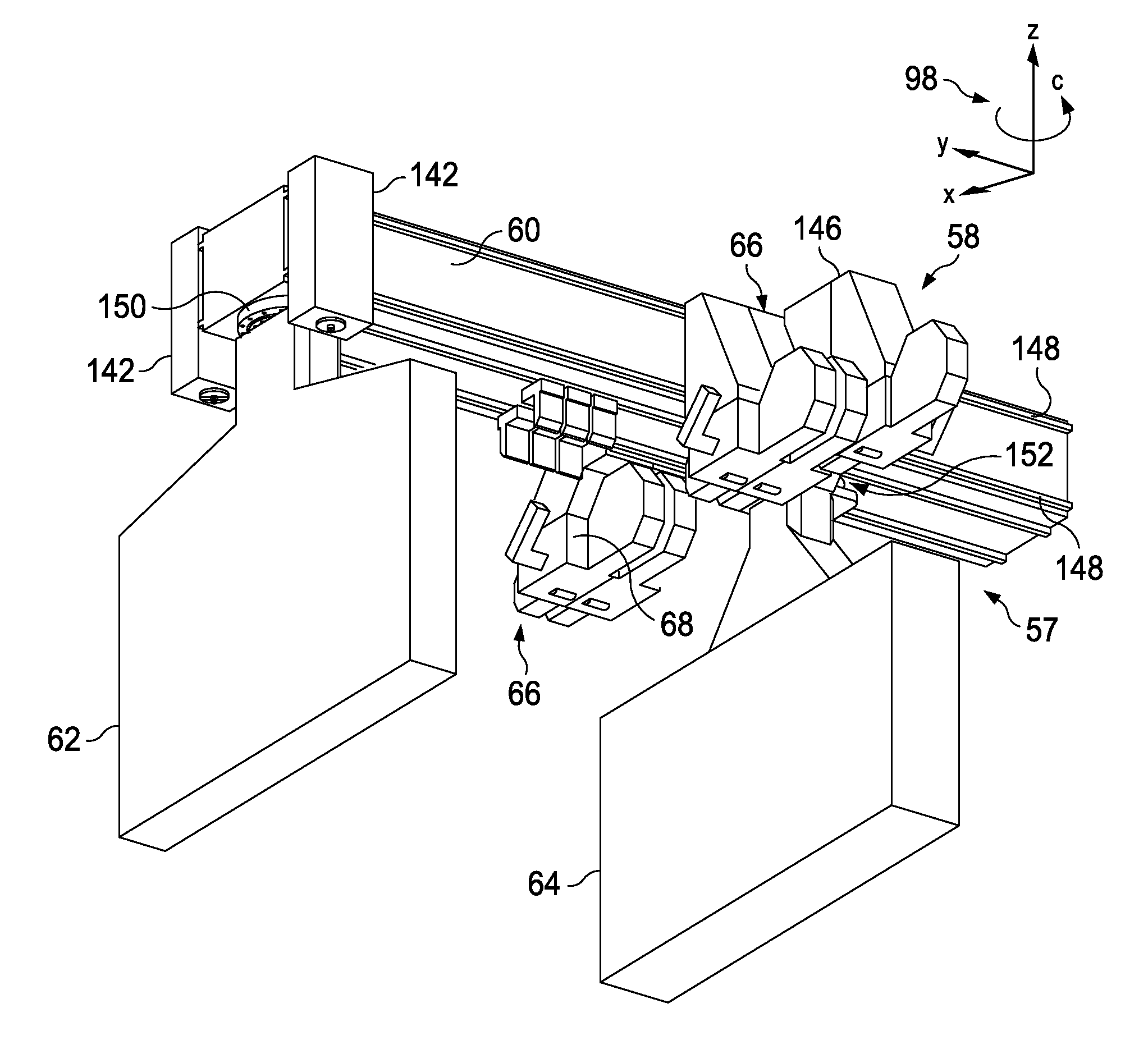
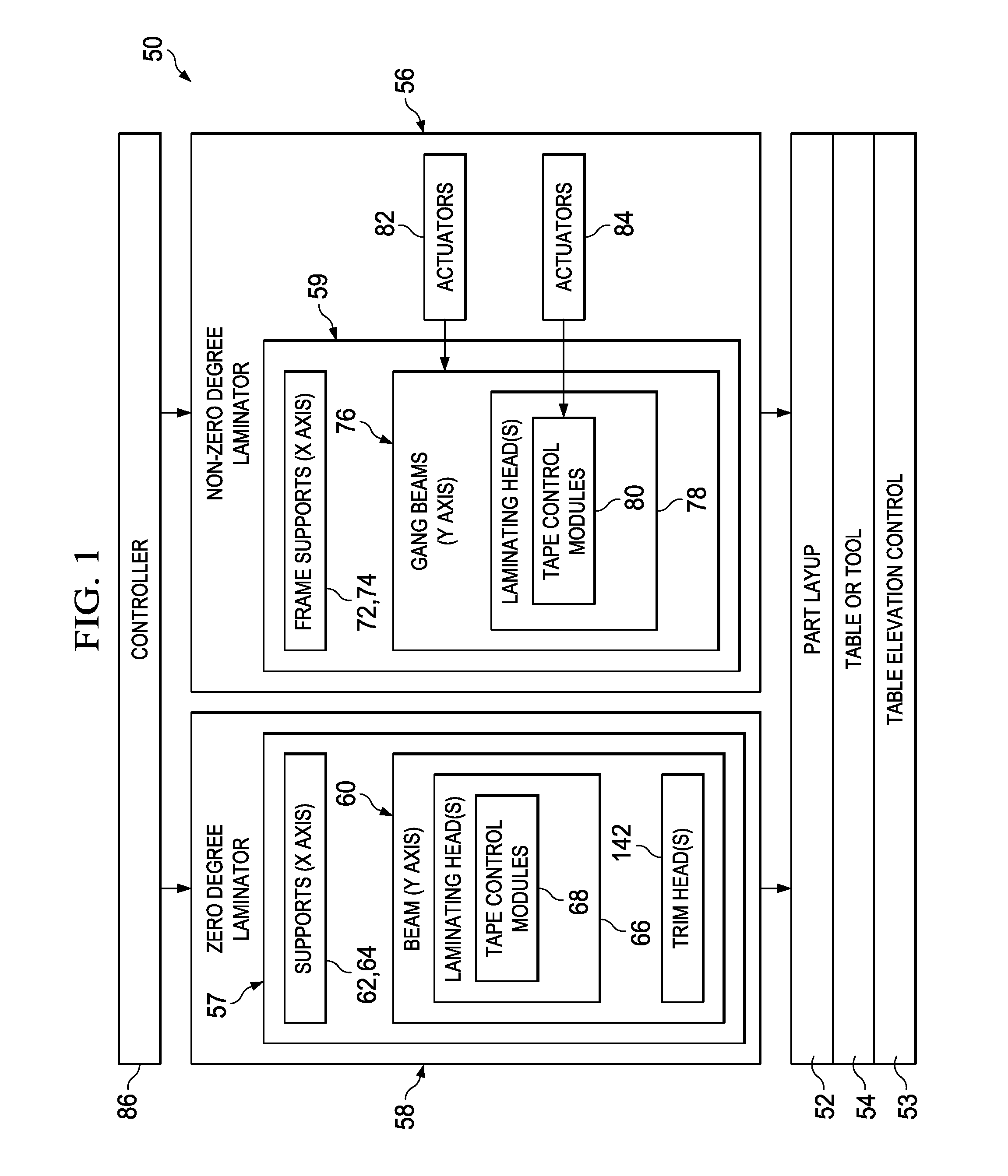
[0058]Referring first to FIG. 1, laminating apparatus 50 for laying up a composite part 52 on a substrate which may comprise table 54 or tool, broadly comprises first and second laminators 56, 58 each automatically operated by a controller 86 which may comprise a PC, PLC (programmable logic controller) or other electronic controller. The table or substrate 54 and the laminators 56, 58 are relatively movable; in the illustrated embodiment, the laminators 56, 58 are independently movable relative to the table 54, however, in other embodiments, this relative movement may be achieved by moving the table 54 relative to the laminators 56, 58. The table 54 may include a table elevation control 53 for controlling the elevation of the table 54, and thus of the vertical distance between the part layup 52 and the laminators 56, 58. The part layup 52 may comprise multiple plies (not shown) of laminated composite tape, wherein each of the plies is formed by laminating multiple courses of unidire...


PUM

PropertyMeasurementUnit
Lengthaaaaaaaaaa
Angleaaaaaaaaaa
Speedaaaaaaaaaa

Abstract

Composite tape is laminated onto a substrate using a gantry to move a tape laminating head along the length of the substrate. The laminating head is mounted for movement along a beam on the gantry that extends across the width of the substrate. The direction of lamination may be altered by changing the angular orientation of the beam.

Description

BACKGROUND INFORMATION[0001]1. Field[0002]The present disclosure generally relates to fabrication of composite structures, and deals more particularly with a method and apparatus for laying up structures using automated ply lamination.[0003]2. Background[0004]Composite structures such as those used in the automotive, marine and aerospace industries may be fabricated using automated composite material application machines, commonly referred to as automated fiber placement (AFP) machines and composite tape layup machines (CTLMs). These machines may be used in aerospace applications, for example, to fabricate large scale structures by placing a plurality of tape strips in continuous, edge-to-edge contact forming a single wide conformal bandwidth that is compacted onto a tool.[0005]The machines described above employ fiber placement heads that have a relatively high degree of operational flexibility, including the ability to add, drop off or cut any or all of contiguous tape strips inde...

Claims


Application Information

Patent Timeline
IPC IPC(8): B32B38/10B32B37/00
CPCB29C70/388Y10T156/17B29C70/30B65H35/08B65H35/008Y02T50/433Y10T156/1795Y10T156/12Y10T156/1093Y10T156/1085Y10T156/1092Y10T156/1077Y10T156/108Y10T156/1378Y10T156/125Y10T156/1074B29C70/545B29C2793/0027Y10T156/1348Y10T156/1788B29C70/38B32B38/0004B32B37/18Y02T50/40
Inventor HAGMAN, THOMAS J.BRANCH, GREGORY LOWMANDWYER, JAMES P.HOOD, BRIAN EDWARDLUND, ERIKMORRIS, WADE MATTHEWSCHWEDHELM, JONATHAN RICHARDSTONE, THOMAS C.
Owner THE BOEING CO
Why Eureka
Try Eureka