Transportable, environmentally-controlled equipment enclosure

a technology of environmentally controlled equipment and equipment enclosures, which is applied in the direction of electrical apparatus construction details, indirect heat exchangers, lighting and heating apparatus, etc., can solve the problems of power consumption of equipment sites, significant power consumption of cooling systems, and the most existing “brick and mortar” sites running out of power capacity

Inactive Publication Date: 2013-02-07
POWER DISTRIBUTION
View PDF25 Cites 79 Cited by
  • Summary
  • Abstract
  • Description
  • Claims
  • Application Information

AI Technical Summary

Benefits of technology

[0019]a coolant reservoir mounted close to the ceiling of the container where coolant from the main condenser is pooled to supply sufficien...

Problems solved by technology

A current issue at equipment sites is power consumption.
Most existing “brick and mortar” sites run out of power capacity long before they reach maximum equipment density.
Even though TECEEs can be maintained at a higher temperature than conventional fixed equipment housing structures, power consumption by the cooling system is still a significant issue, and thus much of the prior art has focused on cooling system improvements.
In either of the known pump-based cooling arrangements, however, the pump...

Method used


Image

  • Transportable, environmentally-controlled equipment enclosure
  • Transportable, environmentally-controlled equipment enclosure
  • Transportable, environmentally-controlled equipment enclosure

Examples


Embodiment Construction

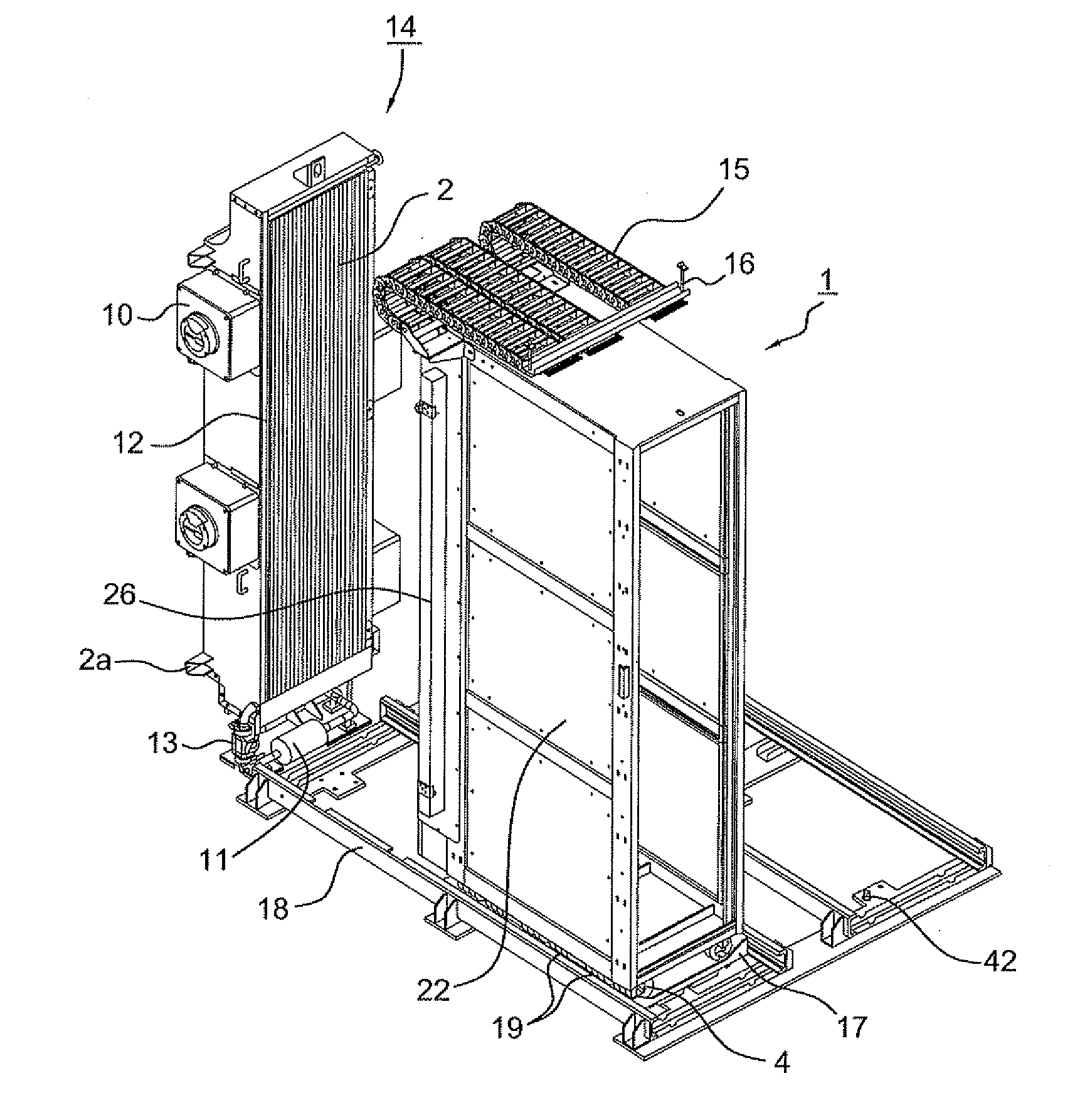
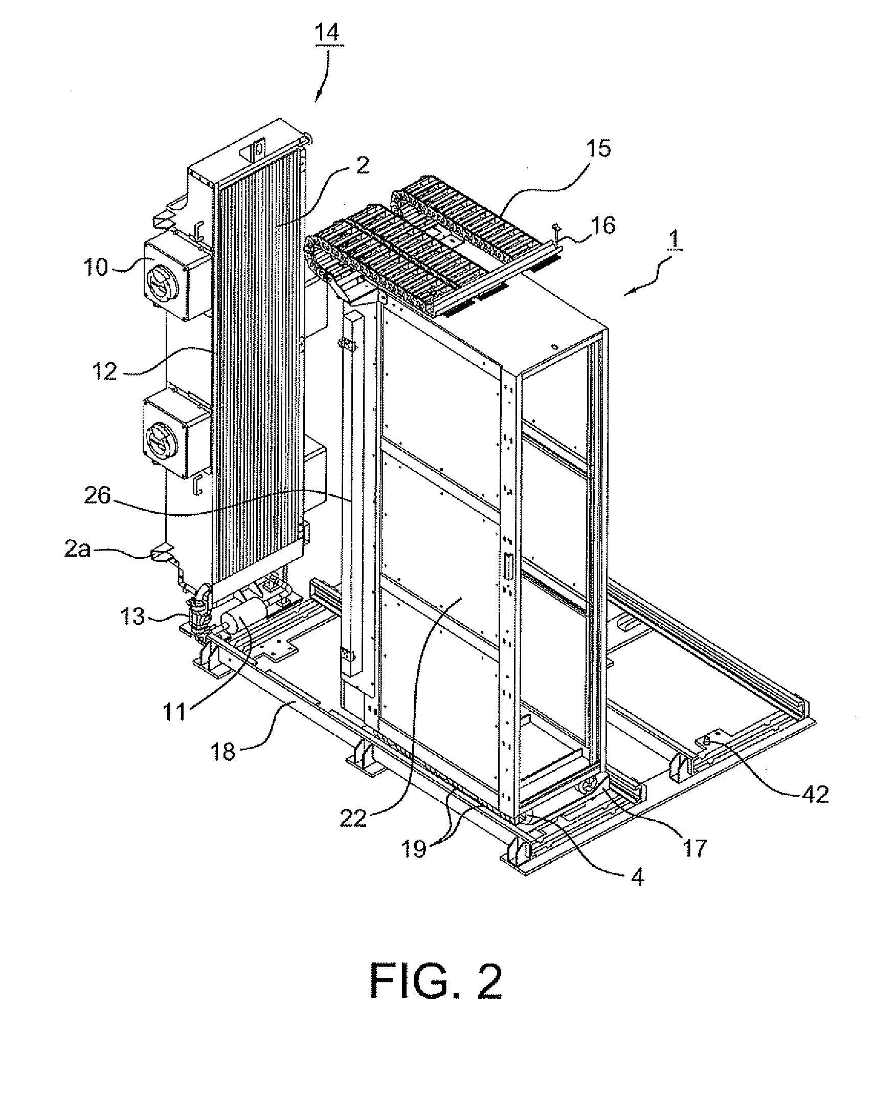
[0045]The preferred embodiments of the invention may be implemented in any transportable, environmentally controlled equipment enclosure, as well as in static or non-transportable equipment enclosures. While specific features of the enclosure exterior and layout are preferred, these features should in general be taken as exemplary and not limiting. In particular, the cooling system and rack mounting arrangements may be separately applicable to a wide variety of different equipment enclosure types, as may various safety and other improvements described below and depicted in the accompanying drawings.

[0046]a. Pump-Less Cooling System

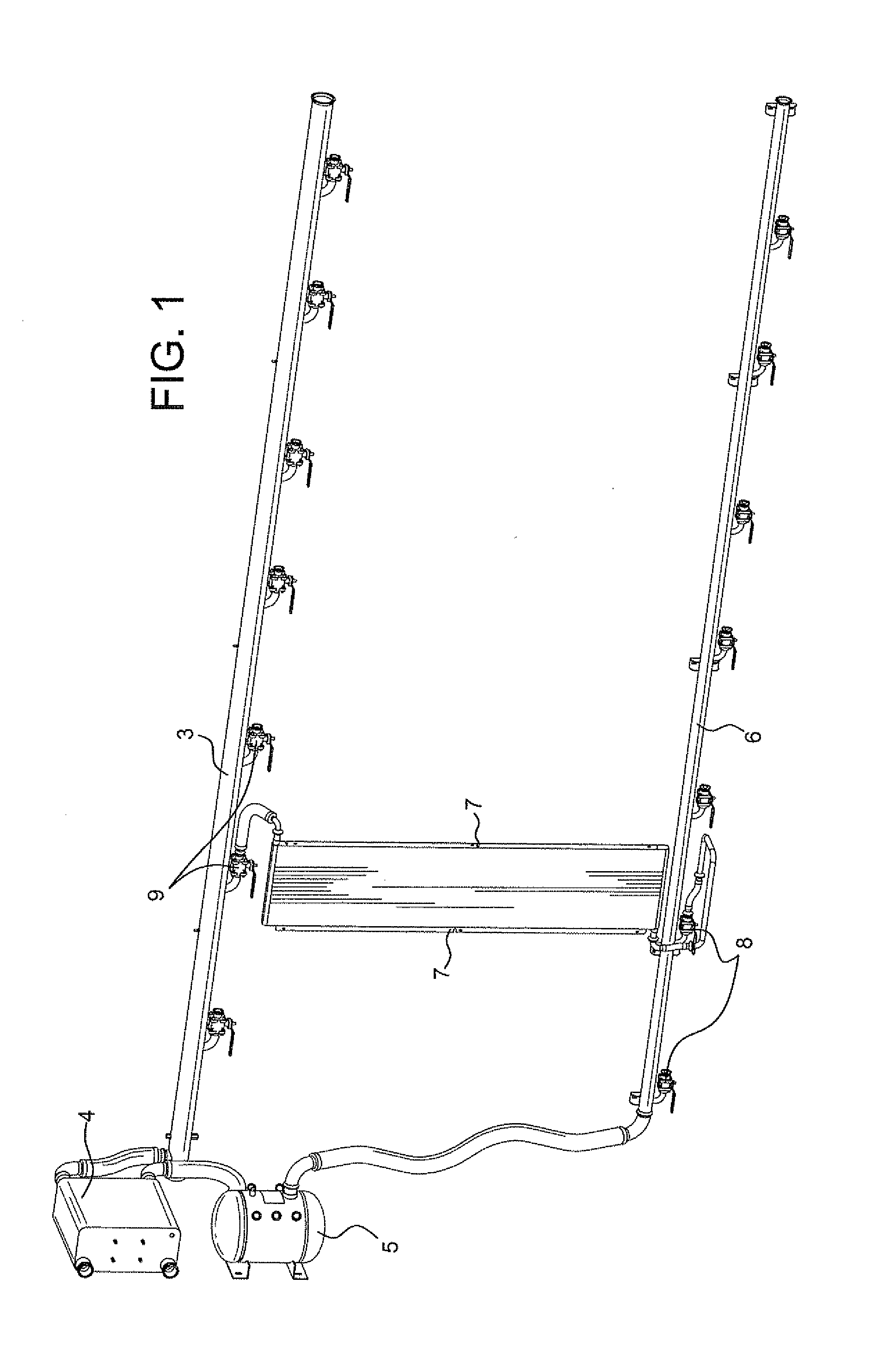
[0047]The cooling system of this preferred embodiment of the invention differs from conventional equipment enclosure cooling systems in that it does not require either a central coolant pump or distributed pumps for the respective enclosures, thereby achieving both power savings and reduced equipment / maintenance costs.

[0048]As illustrated in FIG. 1, the pu...


PUM


Abstract

A transportable environmentally controlled equipment enclosure (TECEE), or other equipment enclosure of the type containing racks of heat-generating equipment, may include a pump-less heat pipe cooling system to carry heat away from the equipment, an improved equipment rack system that includes a suspended base supported by rails with multiple latching and/or locking positions, and various improvements related to power distribution, equipment access, internal and external communications, and safety.

Description

BACKGROUND OF THE INVENTION[0001]1. Field of the Invention[0002]The invention relates to improvements to a Transportable Environmentally Controlled Equipment Enclosure (TECEE) or other equipment enclosure of the type containing racks of heat-generating equipment. By way of example and not limitation, the equipment may be computing equipment and the equipment enclosure may be part of a modular and / or containerized “data center.” Alternatively, the equipment may be ground support, tracking, or communications equipment, or any other equipment requiring a transportable, environmentally controlled enclosure.[0003]The improvements include use of a pump-less heat pipe cooling system to carry heat away from the equipment, an improved equipment rack system that includes a suspended base supported by rails with multiple latching and / or locking positions, and various improvements related to power distribution, equipment access, internal and external communications, and safety.[0004]2. Descript...

Claims


Application Information

Patent Timeline
IPC IPC(8): F28D15/02
CPCF28D15/02H05K7/20818H05K7/1497H05K7/20681E04H2001/1283E04H2005/005
Inventor JAENA, MARIO L.GULKAROV, VLADIMIRCORTES, TIMOTHY MARTINSCHMID, KEITH
Owner POWER DISTRIBUTION
Why Eureka
Try Eureka