Power tool and operation method for the power tool
- Summary
- Abstract
- Description
- Claims
- Application Information
AI Technical Summary
Benefits of technology
Problems solved by technology
Method used
Image
Examples
third embodiment
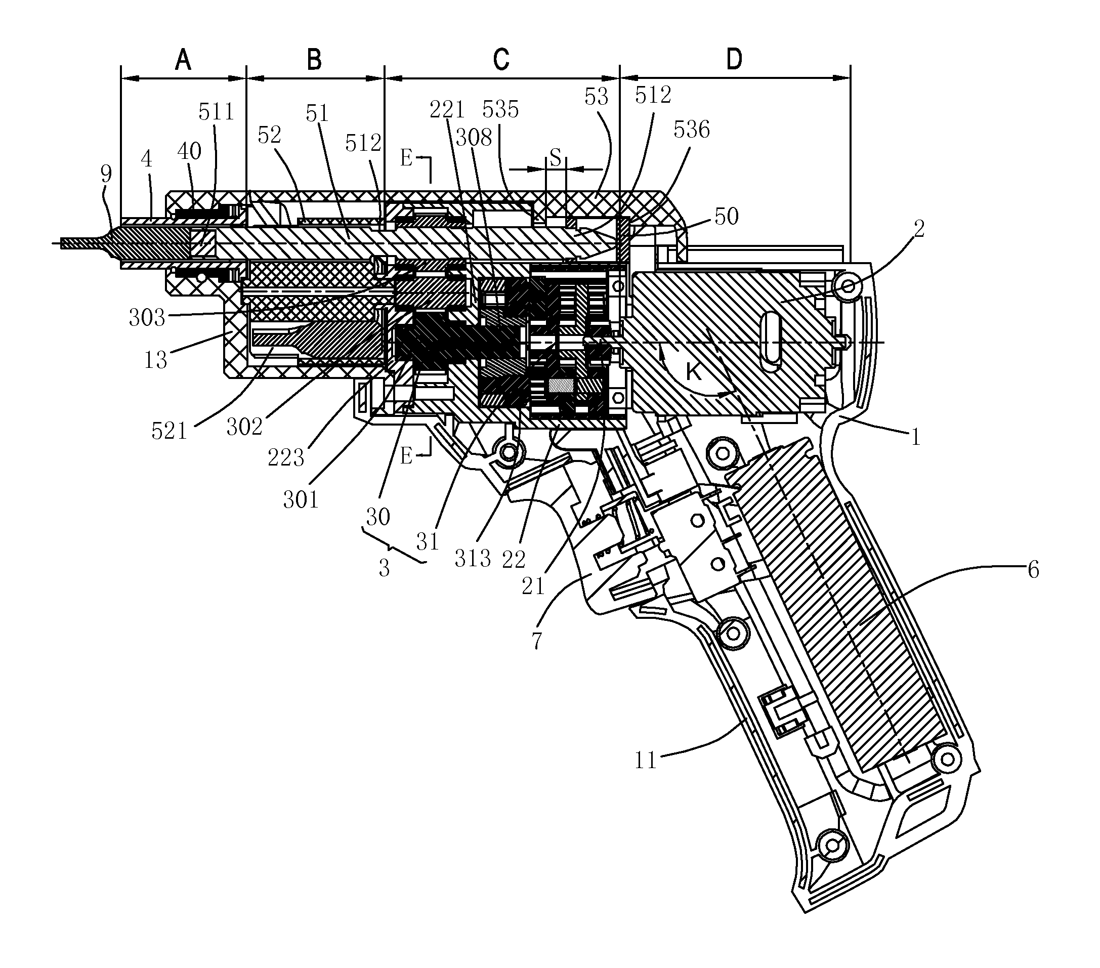
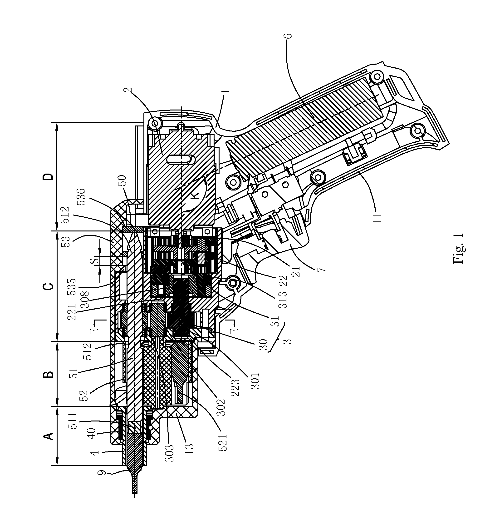
[0270]FIG. 16 and FIG. 17 illustrate the restricting mechanism 8. The restricting mechanism 8b comprises a restricting member 81b and a spring 83b; the restricting member 81b is axially fixed with respect to the housing 1; the restricting member 81b can move linearly in a direction vertical to the axis of the connecting shaft 51; one end of the spring 83b is received in the restricting member 81b, while the other end is connected with the housing 1 or the gear case 22; and the spring 83b eccentrically presses the restricting member 81b to keep the restricting member at the first position (as shown in FIG. 16) where the restricting member is axially pressed against the fixed member 50. In this embodiment, the inclined plane 533 of the slip cover 53 interacts with the restricting member 81b to release the restriction on the axial movement of the fixed member 50; and the restricting member 81b overcomes the spring force of the spring 83b to move linearly to the second position (as show...
first embodiment
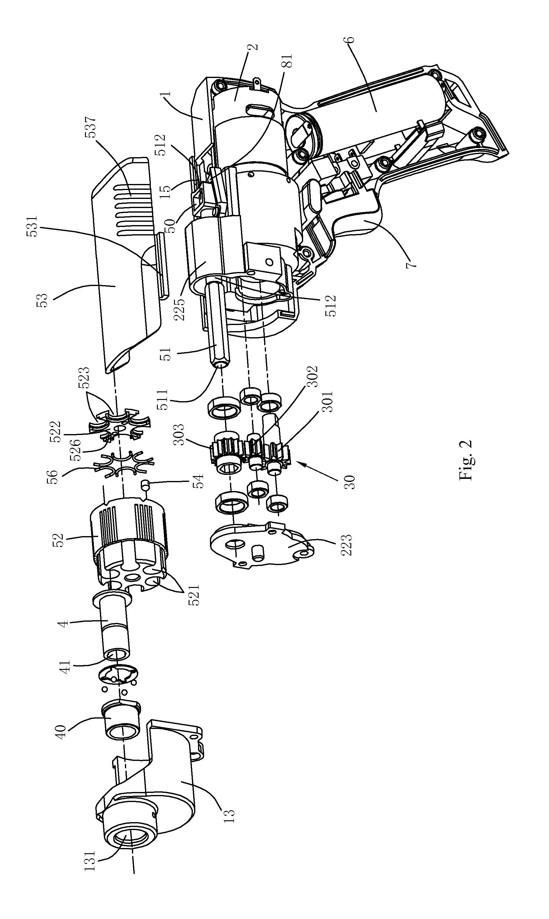
[0277]FIG. 5 and FIG. 18 illustrate the removable cartridge. The upper part of the front housing 13 is provided with an open portion 133, and the bottom part of the front housing 13 is provided with a radial open pore 134 radially opposite to the open portion 133; when the cartridge 52 is required to be replaced, the slip cover 53 is operated to move toward the motor 2, and then the connecting shaft 51 moves with the slip cover 53 to the position where the connecting shaft 51 is separated from the cartridge 52; in this way, the cartridge 52 can be ejected and removed by directly sticking the radial open pore 134 with a finger, and then the cartridge provided with a different tool bit is installed into the housing from the open portion 133. The cartridge 52 is supported by contacting with the circular face of the front housing 13. Of course, to reduce the friction generated between the cartridge 52 and the front housing 13 when the cartridge is rotating, the inner wall of the front h...
second embodiment
[0278]FIG. 19 illustrates the removable cartridge. The bottom of the front housing 13 is provided with a rubber cushion 135 for sealing the radial open pore 134. The rubber cushion 135 has certain elasticity, so the operation that the cartridge 52 is ejected from the radial open pore 134 when the cartridge 52 is replaced is not influenced, and meanwhile the front housing 13 can be sealed to prevent foreign bodies such as dust from entering the housing. Of course, those skilled in this field can easily figure out that a spring plate at the open pore 134 can also achieve the same effect. Or, the button which can axially move with respect to the connecting shaft is directly installed in the radial open pore 134; when the cartridge is required to be ejected, the cartridge can be taken out by pressing the button, and the button can drop down by the action of the dead weight. Of course, a spring can be installed between the button and the front housing, and the button is kept separated fr...
PUM
 Abstract
Description
Claims
Application Information
 - R&D
- Intellectual Property
- Life Sciences
- Materials
- Tech Scout
- Unparalleled Data Quality
- Higher Quality Content
- 60% Fewer Hallucinations
Browse by: Latest US Patents, China's latest patents, Technical Efficacy Thesaurus, Application Domain, Technology Topic, Popular Technical Reports.
© 2025 PatSnap. All rights reserved.Legal|Privacy policy|Modern Slavery Act Transparency Statement|Sitemap|About US| Contact US: help@patsnap.com


