Fluid processing apparatus

Active Publication Date: 2013-02-14
QUANTA DIALYSIS TECH LTD
View PDF4 Cites 80 Cited by
  • Summary
  • Abstract
  • Description
  • Claims
  • Application Information

AI Technical Summary

Benefits of technology

[0006]Accordingly it is an object of the present invention to provide an improved

Problems solved by technology

Often these systems have been complex requiring either a disposable flexible bag-like circuit to be placed in a non-disposable rigid supporting structure prior to inserting into the machine or requiring tubes to be connected to various elements of a non-disposable component prior to interfacing with the machine.
While these designs go some way to providing a solution to the cleaning problem, they are complex and there is scope for

Method used


Image

  • Fluid processing apparatus
  • Fluid processing apparatus
  • Fluid processing apparatus

Examples


Embodiment Construction

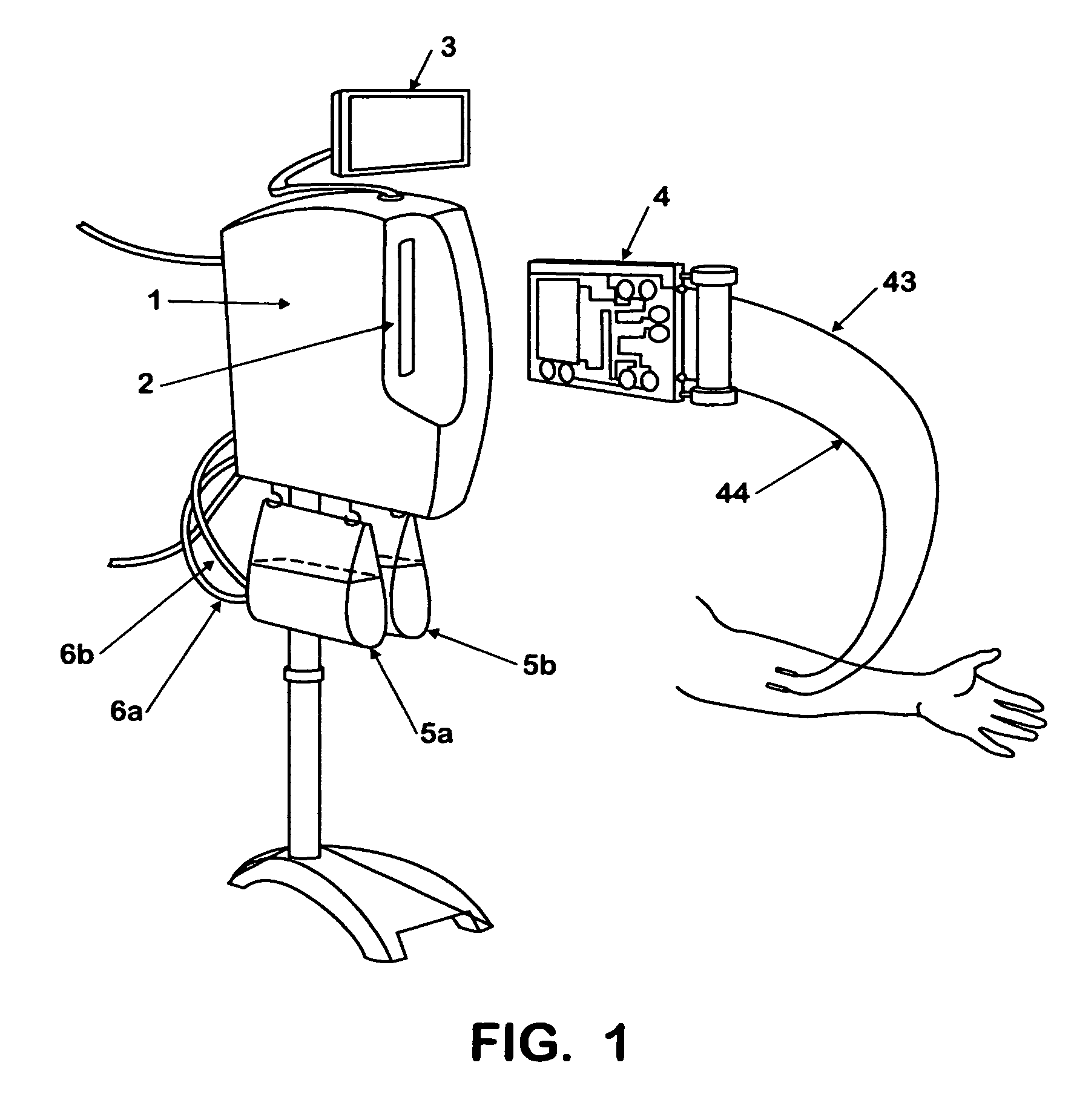
[0042]Referring to FIG. 1, a haemodialysis system is shown which comprises a machine 1 containing a slot 2 adapted to accept and retain therein a cartridge 4, and an operator interface 3. The combination of machine and cartridge together, when connected to a patients circulatory system, perform an extracorporeal haemodialysis process on the patients blood before returning it to the patient. The operator interface 3 both permits control of the dialysis functions, and provides status and warning information as required.

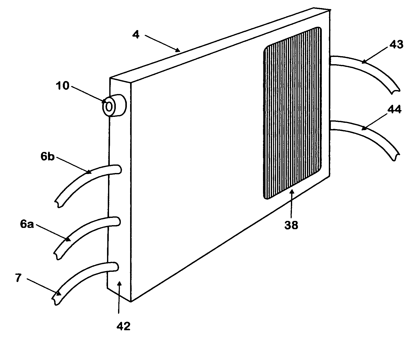
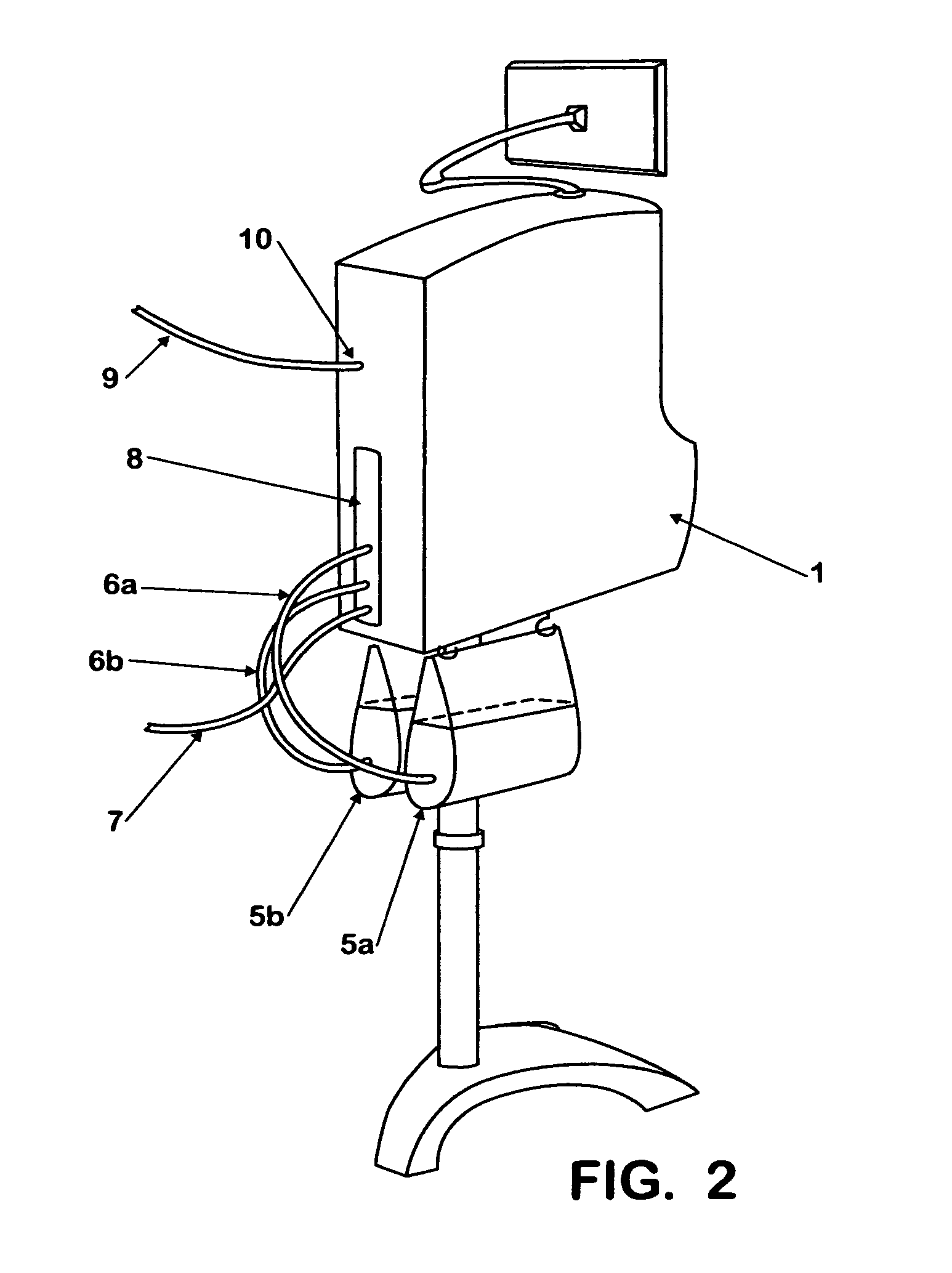
[0043]Referring to FIGS. 1 and 2 when the cartridge 4 is inserted into the slot 2 of the machine 1, an aperture 8 at the rear of the machine provides access to couple a drain tube 7 and one or more supplementary supply tubes 6a, 6b directly to the rear of the cartridge 4. The tubes 6a, 6b draw supplementary additives from containers 5a, 5b which are shown mounted under the machine 1. An external deionised water supply pipe 9 connects directly to the machine through wate...


PUM

PropertyMeasurementUnit
Angleaaaaaaaaaa
Temperatureaaaaaaaaaa
Residual entropyaaaaaaaaaa

Abstract

A machine is provided with a slot to releasably receive and retain a cartridge in which dialysis is effected. The machine is configured for supplying to the cartridge, at a controlled temperature and rate, sterile water for use in haemodialysis and is operable to maintain, in a sterile condition, residual water contained therein after completion of a haemodialysis treatment.

Description

[0001]This application is a continuation of application Ser. No. 11 / 919,600, filed Jan. 26, 2009, which in turn is a national stage application of International Application No. PCT / GB2006 / 001671 with an International filing date of May 8, 2006.FIELD OF THE INVENTION[0002]This invention relates to apparatus for the extracorporeal processing of bodily fluids, in particular the extracorporeal dialysis of blood.BACKGROUND OF THE INVENTION[0003]Most dialysis apparatus currently in use must be very rigorously cleaned between uses to prevent contamination, either cross-contamination from one fluid to another or contamination, with for example bacteria, due to poor sanitation. This is particularly important in haemodialysis, which comprises removing blood from the body, processing it by means of diffusion exchange through a membrane with a dialysis solution, and then returning it to the body. In attempt to reduce the amount of cleaning required, various methods and apparatus have been devel...

Claims


Application Information

Patent Timeline
IPC IPC(8): C02F1/02
CPCA61M1/16A61M1/1656A61M1/1635A61M2205/12A61M1/3621A61M1/1686A61M2205/3317A61M2205/3324A61M2205/3382A61M2205/3386A61M1/1668A61M1/155A61M1/1565A61M1/362227A61M1/1524A61M1/1566A61M1/362265A61M1/362264A61M1/15632A61M1/362261A61M1/1561A61M1/362266A61M1/36225
Inventor HEYES, KEITH JAMESBRAMLEY, HUGH CHRISTOPHERBHIMANI, ALAN MELVYN
Owner QUANTA DIALYSIS TECH LTD
Why Eureka
Try Eureka