

Nozzle for Cutting Steel Workpieces and Workpieces Made of Iron Alloys
a technology of cutting nozzles and workpieces, which is applied in the direction of gas flame welding apparatus, combustion process, lighting and heating apparatus, etc., can solve the problems of workpiece burning, etc., and achieve the effect of reducing drilling work, reducing drilling costs, and reducing overall length of nozzles or nozzle bodies
Inactive Publication Date: 2013-02-14
FUR AUTOGENMASCH UND GERATE MBH
View PDF2 Cites 6 Cited by
- Summary
- Abstract
- Description
- Claims
- Application Information
AI Technical Summary
Benefits of technology
The invention is a new type of nozzle for torch-cutting workpieces made of steel and iron alloys. It is designed to be economical to manufacture, protected against impurities, and efficient in its cutting performance. The nozzle features a cooling system with oxygen holes that create an air curtain to protect the cutting flame from dirt particles and prevent contamination. The nozzle has a one-piece design or a direct demarcation of the outlet surface and pot-shaped, cylindrical free space by the hexagon head, which reduces the likelihood of cinders deposition and minimizes drilling work needed. These technical improvements result in a more efficient and reliable nozzle for industrial use.
Problems solved by technology
In the process, the workpiece starts to burn and forms a gap that extends into a cut when the jet continues on.
Method used
View moreImage
Smart ImageViewing Examples

Examples
first embodiment
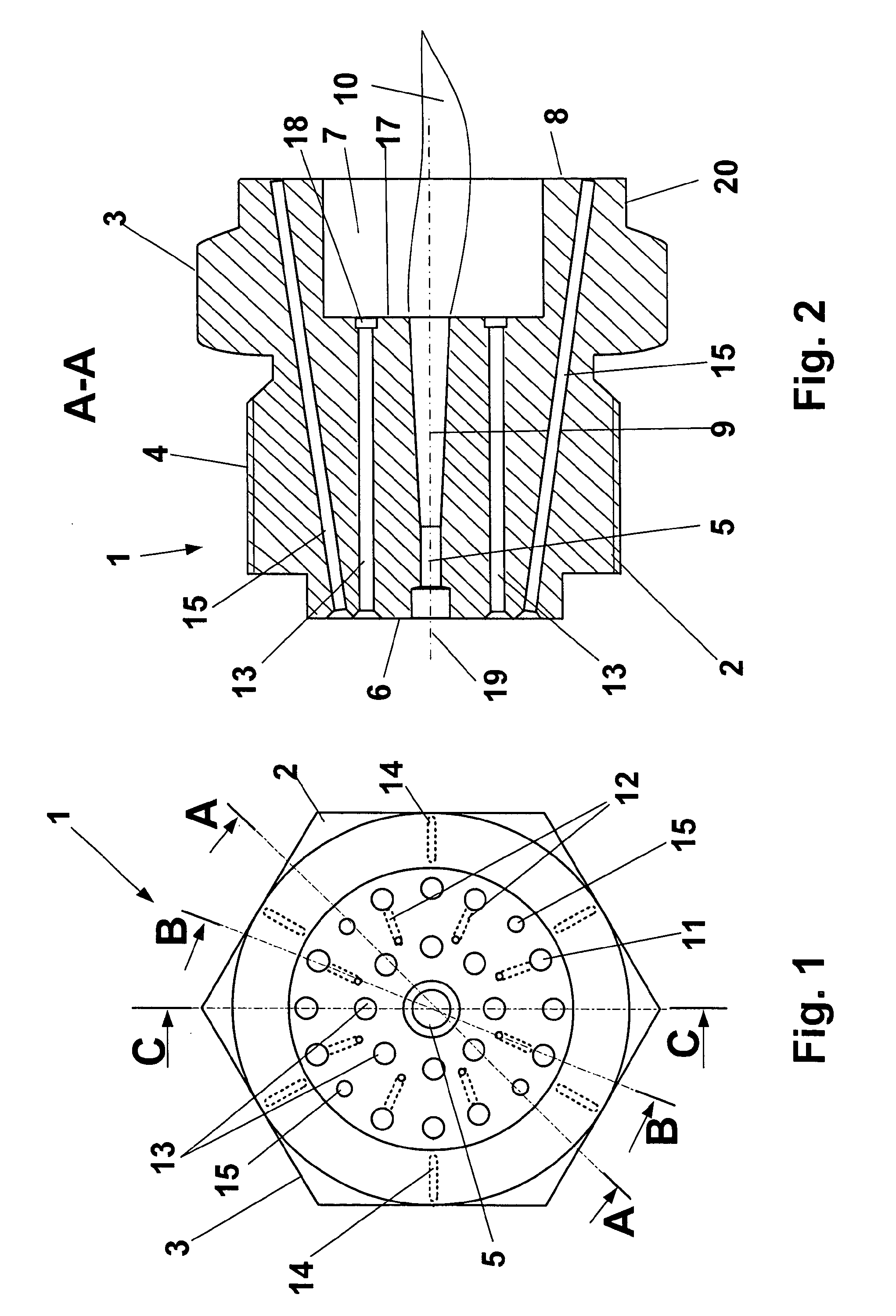
[0024]FIG. 1 shows a frontal view on the inlet side of the nozzle as per the invention in a first embodiment,
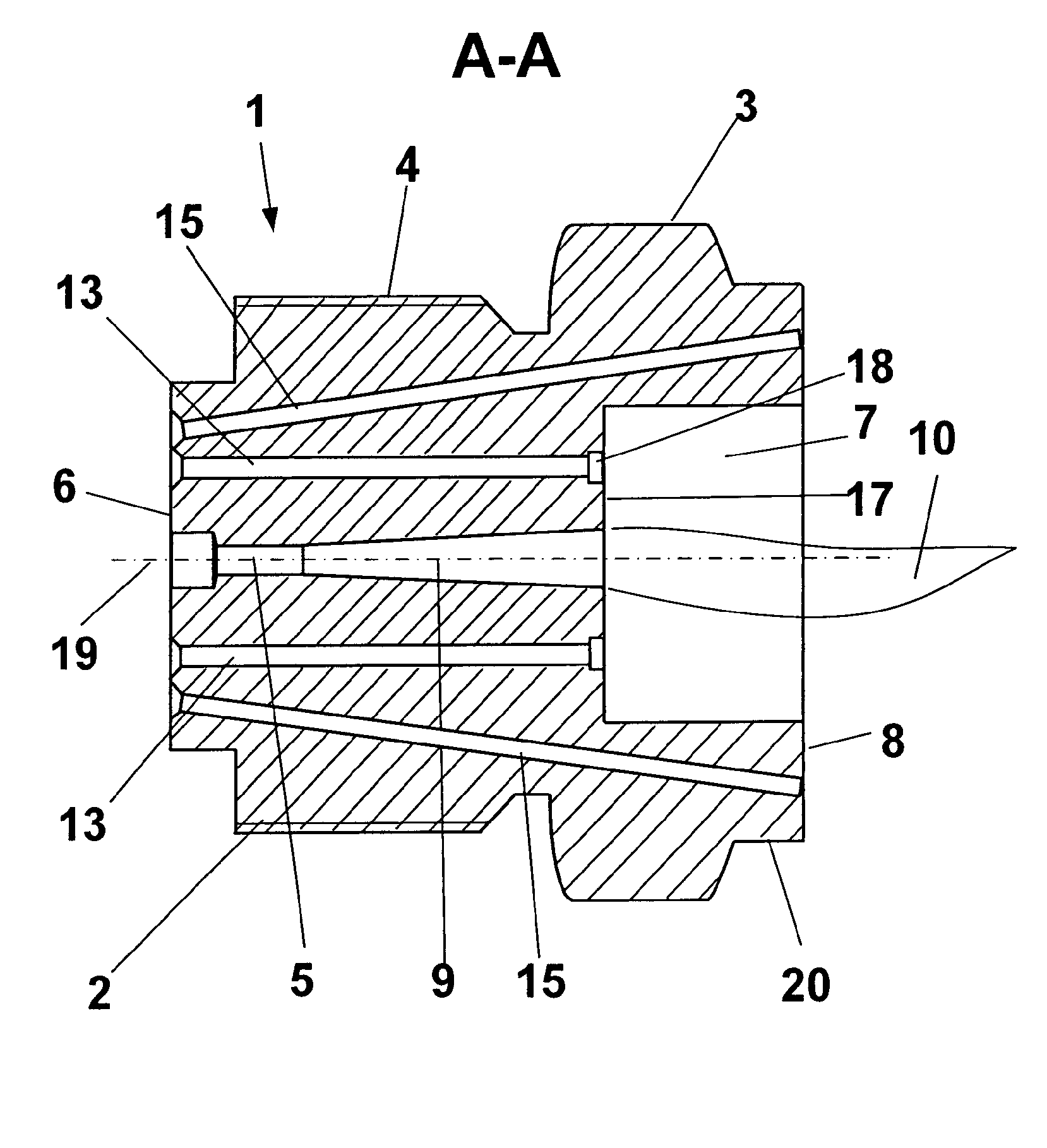
[0025]FIG. 2 shows a side view of the nozzle along the line A-A in accordance with FIG. 1,
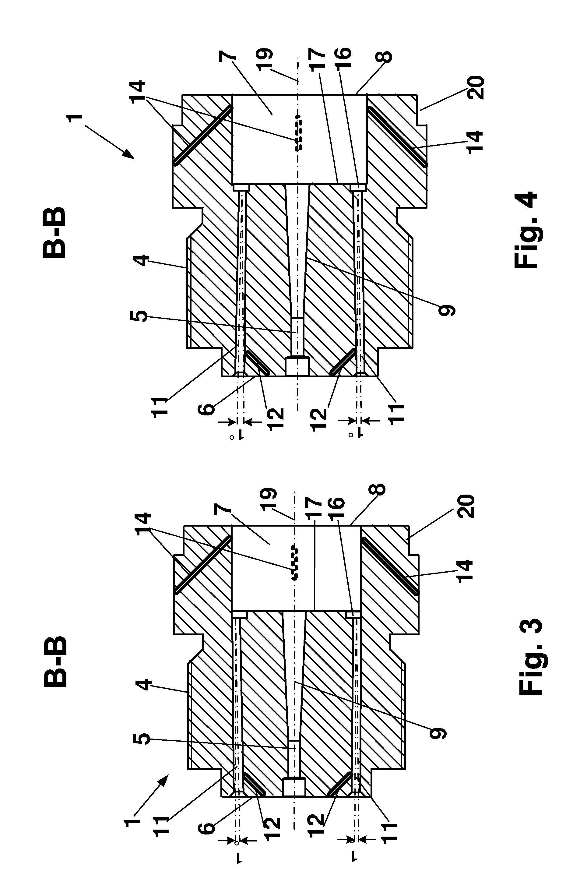
[0026]FIG. 3 shows a side view of the nozzle along the line B-B in accordance with FIG. 1,
[0027]FIG. 4 shows a side view of the nozzle along the line B-B in accordance with FIG. 1 in an alternative embodiment in accordance with FIG. 3,
[0028]FIG. 5 shows a side view of the nozzle along the line C-C in accordance with FIG. 1, and
second embodiment
[0029]FIG. 6 shows a side view of the nozzle in a
[0030]Functionally equivalent components have been given the same reference numeral in all of the figures.
Login to View More PUM
| Property | Measurement | Unit |
|---|---|---|
| angle | aaaaa | aaaaa |
| angle | aaaaa | aaaaa |
| ignition temperature | aaaaa | aaaaa |
Abstract
The invention relates to a nozzle (1) for cutting steel workpieces and workpieces made of iron alloys, comprising a nozzle body (2) having an axial hole (5) for the discharge of cutting oxygen and a cylindrical free space (7) at the outlet surface (8) of the nozzle (1), which outlet surface forms the cutting flame (10). The nozzle (1) further comprises a plurality of heating gas holes (13) and a plurality of heating oxygen holes (11), which are arranged in an outer or inner concentric circle around the axial hole (5). In addition, a number of cooling oxygen holes (15) arranged in at least one concentric circle around the axial hole (5) is provided. The cooling oxygen holes run from the inlet side (6) of the nozzle body (2) to the outlet surface (8) of the nozzle (1) and open outside of the pot-shaped cylindrical free space (7).
Description
CROSS REFERENCE TO RELATED APPLICATIONS[0001]This application is the U.S. national stage of International Application No. PCT / EP2010 / 052412, filed on Feb. 25, 2010, and claims the benefit thereof. The international application is incorporated by reference herein in its entirety.BACKGROUND[0002]The invention relates to a nozzle for cutting steel workpieces and workpieces made of iron alloys, comprising a nozzle body with[0003]an axial hole for the cutting oxygen and a pot-shaped, cylindrical free space at the outlet surface of the nozzle forming the cutting flame,[0004]a plurality of heating oxygen holes and heating gas holes that are arranged in concentric circles around the axial hole, and[0005]a hexagon head, if necessary, for screwing the nozzle onto a cutting torch.[0006]Oxygen-fuel gas cutting torches are intended to be used to cut steel workpieces and workpieces made of iron alloys. Blocks and slabs are effectively cut with that, for example. In so doing, the flame of the gas ...
Claims
Login to View More Application Information
Patent Timeline
 Patent Type & AuthorityApplications(United States)
IPC IPC(8): B23K7/00
CPCF23D14/54
InventorLOTZ, HORST
OwnerFUR AUTOGENMASCH UND GERATE MBH