
Asymmetric angular response pixels for single sensor stereo

a single sensor, angular response technology, applied in the field of imaging systems, can solve the problems of increasing cost and complexity in obtaining good stereo imaging performance, reducing spatial resolution, and increasing cost and complexity

Active Publication Date: 2013-02-14
SEMICON COMPONENTS IND LLC
View PDF40 Cites 37 Cited by
  • Summary
  • Abstract
  • Description
  • Claims
  • Application Information

AI Technical Summary

Benefits of technology

The present invention is about an improved imaging system that uses depth sensing pixels to obtain stereo performance with a single sensor and a single lens. This reduces complexity and cost compared to conventional arrangements. The invention includes a microlens with asymmetric angular response and asymmetrically sensitive depth sensing pixels. The invention also includes a depth sensing pixel that can focus light from an object at varying distances from the sensor. The invention can be used in electronic devices such as cameras, camcorders, and computers to obtain better stereo imaging performance.

Problems solved by technology

These increase cost and complexity in obtaining good stereo imaging performance.
Due to the addition of components, such as complex lens arrays, these arrangements lead to reduced spatial resolution, increased cost and complexity.

Method used


Image

  • Asymmetric angular response pixels for single sensor stereo
  • Asymmetric angular response pixels for single sensor stereo
  • Asymmetric angular response pixels for single sensor stereo

Examples


Embodiment Construction

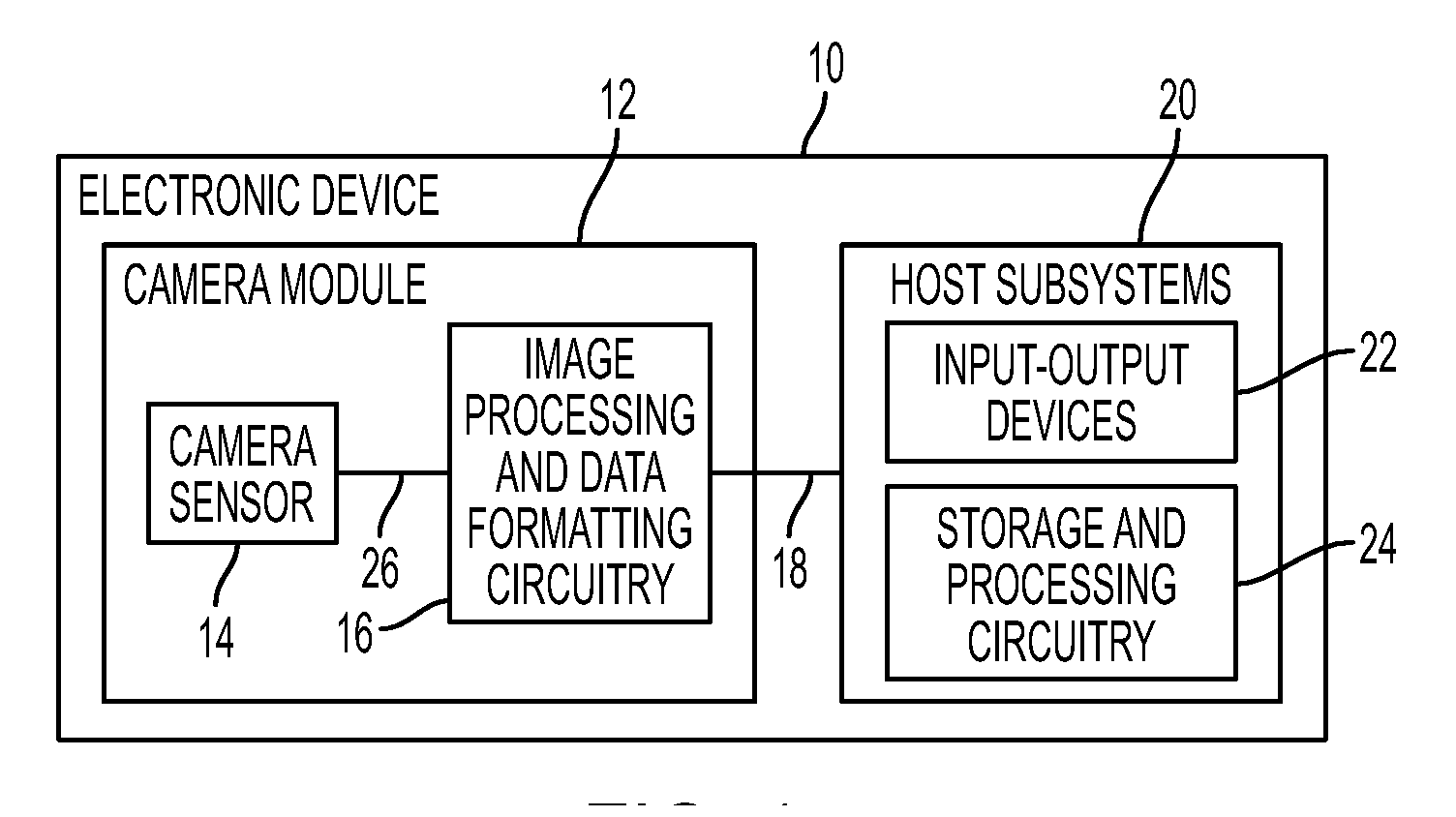
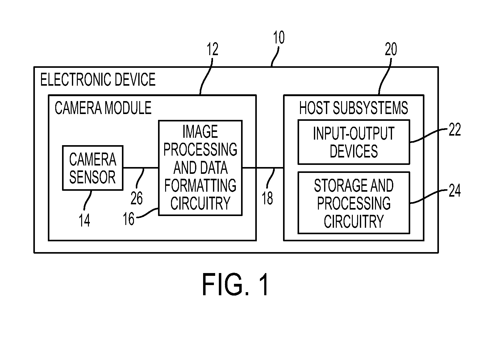
[0024]An electronic device with a digital camera module is shown in FIG. 1. Electronic device 10 may be a digital camera, a computer, a cellular telephone, a medical device, or other electronic device. Camera module 12 may include image sensor 14 and one or more lenses. During operation, the lenses focus light onto image sensor 14. Image sensor 14 includes photosensitive elements (i.e., pixels) that convert the light into digital data. Image sensors may have any number of pixels (e.g., hundreds, thousands, millions, or more). As examples, image sensor 14 may include bias circuitry (e.g., source follower load circuits), sample and hold circuitry, correlated double sampling (CDS) circuitry, amplifier circuitry, analog-to-digital converter (ADC) circuitry, data output circuitry, memory (e.g., buffer circuitry), address circuitry, etc.

[0025]Still and video image data from camera sensor 14 may be provided to image processing and data formatting circuitry 16 via path 26. Image processing ...


PUM


Abstract

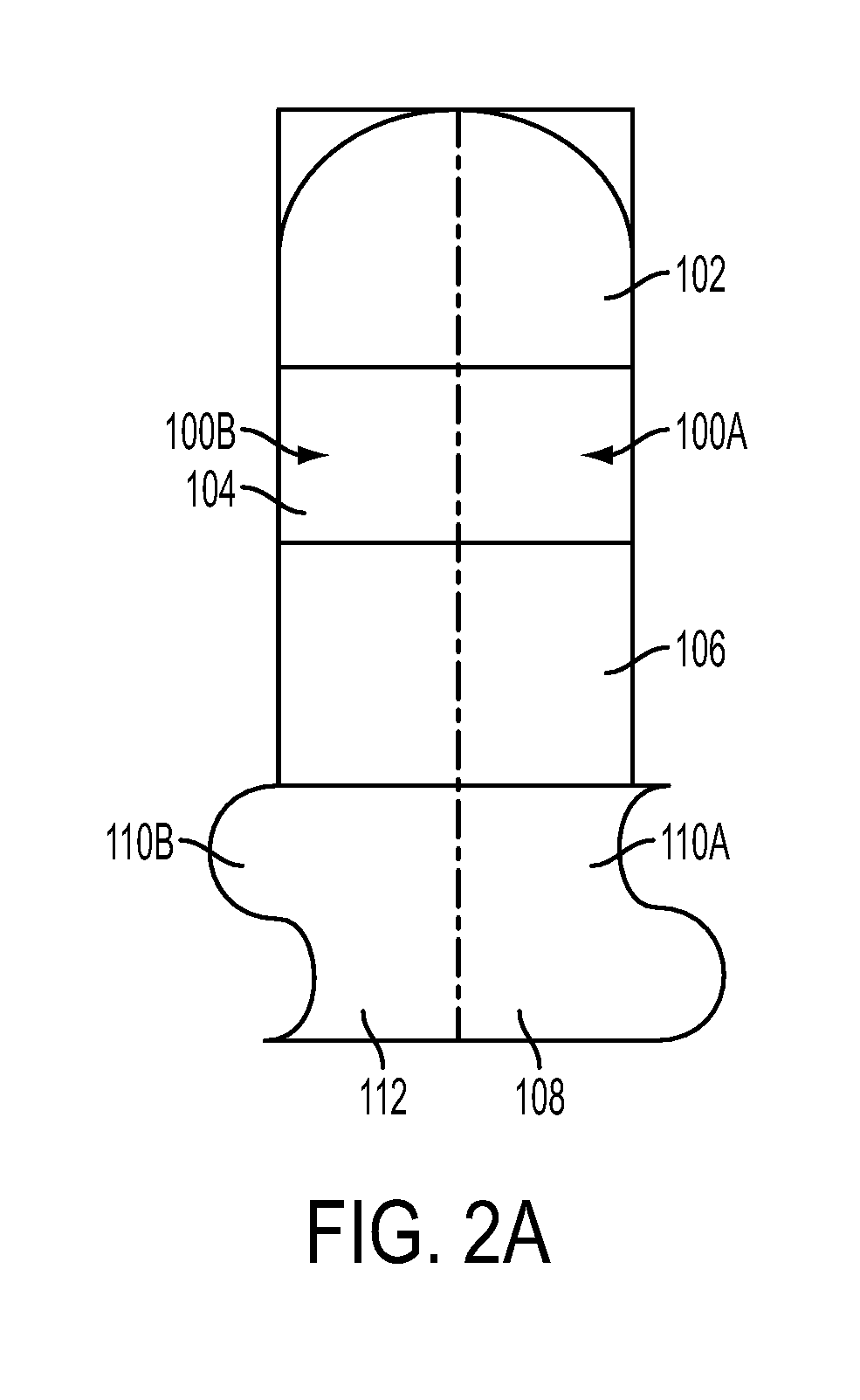
Depth sensing imaging pixels include pairs of left and right pixels forming an asymmetrical angular response to incident light. A single microlens is positioned above each pair of left and right pixels. Each microlens spans across each of the pairs of pixels in a horizontal direction. Each microlens has a length that is substantially twice the length of either the left or right pixel in the horizontal direction; and each microlens has a width that is substantially the same as a width of either the left or right pixel in a vertical direction. The horizontal and vertical directions are horizontal and vertical directions of a planar image array. A light pipe in each pixel is used to improve light concentration and reduce cross talk.

Description

CROSS REFERENCE TO RELATED APPLICATIONS[0001]This application claims priority of U.S. Provisional Patent Application Ser. No. 61 / 522,876, filed Aug. 12, 2011, which is incorporated herein by reference.FIELD OF THE INVENTION[0002]The present invention relates, in general, to imaging systems. More specifically, the present invention relates to imaging systems with depth sensing capabilities and stereo perception, although using only a single sensor with a single lens.BACKGROUND OF THE INVENTION[0003]Modern electronic devices such as cellular telephones, cameras, and computers often use digital image sensors. Imagers (i.e., image sensors) may be formed from a two-dimensional array of image sensing pixels. Each pixel receives incident photons (light) and converts the photons into electrical signals.[0004]Some applications, such as three-dimensional (3D) imaging may require electronic devices to have depth sensing capabilities. For example, to properly generate a 3D image for a given sce...

Claims


Application Information

Patent Timeline
Patent Type & Authority Applications(United States)
IPC IPC(8): H04N13/02
CPCH04N13/0228H04N5/3696H04N13/229H01L27/14621H01L27/14627H04N25/134H04N25/703H04N25/704H04N25/702
Inventor AGRANOV, GENNADIYCAO, DONGQINGYARON, AVI
Owner SEMICON COMPONENTS IND LLC
Learn More