Bidirectional multimode power converter

a power converter and multi-mode technology, applied in the direction of dc-dc conversion, climate sustainability, power electronics conversion, etc., can solve the problems of large amounts of electrical energy that cannot be stored economically, converters consume power, inefficient incandescent bulbs used for lighting all over the world, etc., to facilitate parallel operation, facilitate fault tolerance and load sharing, and achieve the effect of not compromising the overall conversion efficiency of the converter

Active Publication Date: 2013-02-14
SHARMA VISWA N
View PDF5 Cites 90 Cited by
  • Summary
  • Abstract
  • Description
  • Claims
  • Application Information

AI Technical Summary

Benefits of technology

[0033]In addition, the Bidirectional Multimode Power Converter architecture of the present invention facilitates fault tolerance and load sharing by switching in an additional input source or additional output load into operation as a backup power source or backup load without the use of additional Oring diodes.
[0034]Furthermore, the Bidirectional Multimode Power Converter architecture of the present invention facilitates parallel operation of multiple converters from either AC or DC source or to AC or DC load, to supply a load. It should be appreciated that in such parallel operation the overall conversion ...

Problems solved by technology

Large amounts of electrical energy cannot be stored economically.
Inefficient incandescent bulbs are being used for lighting all over the world.
The converters consume power when they are idle, wasting energy.
The energy wasted due to power converter inefficiencies increases as the number of the converters increase.
So, batteries are limited by the slow chemical conversion time.
Most LPS use linear regulators, which are inefficient and need large heat sinks.
However, multiple stages employed in SMPS reduce the cumulative efficiency of the overall system.
This d...

Method used


Image

  • Bidirectional multimode power converter
  • Bidirectional multimode power converter
  • Bidirectional multimode power converter

Examples


Embodiment Construction

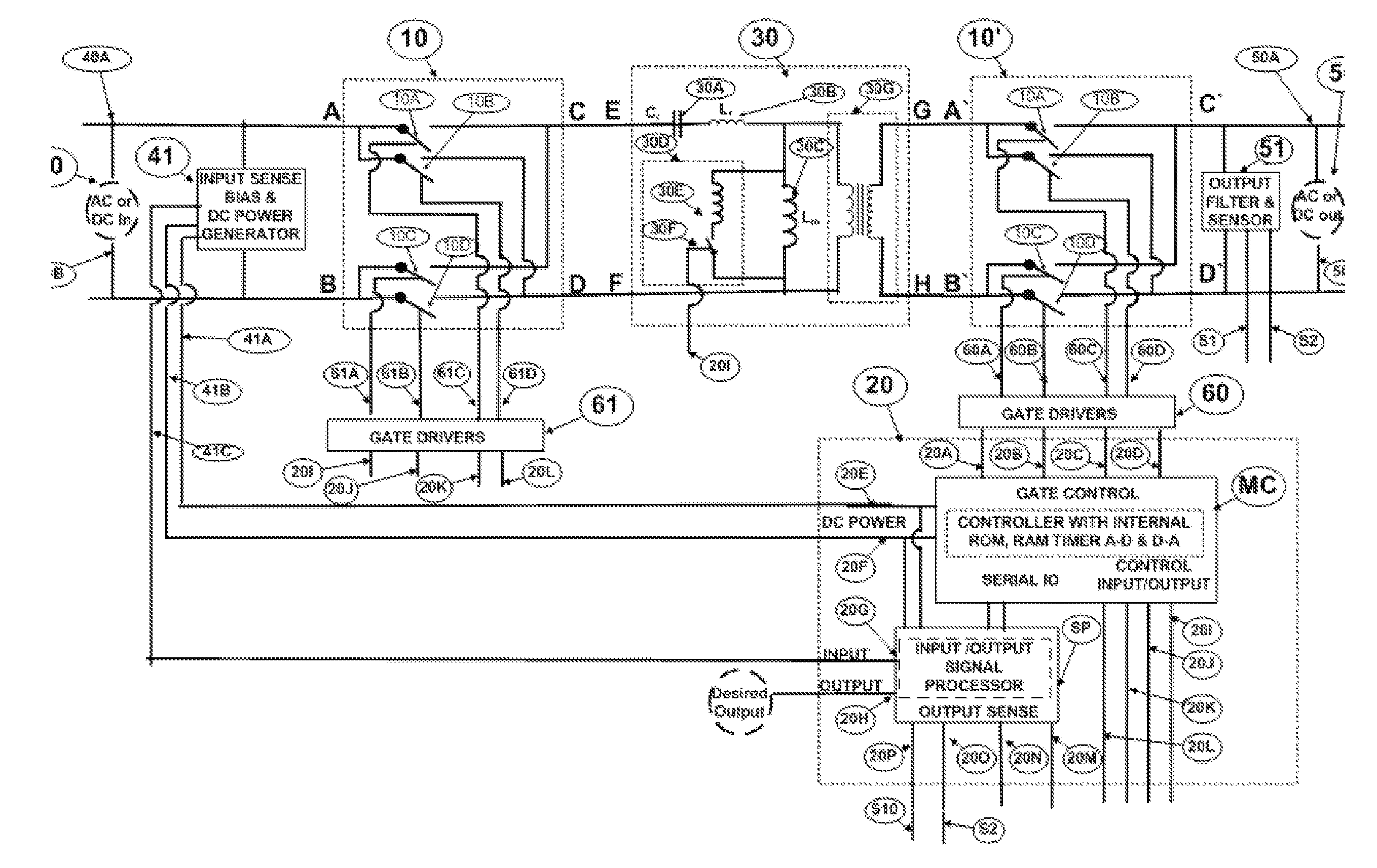
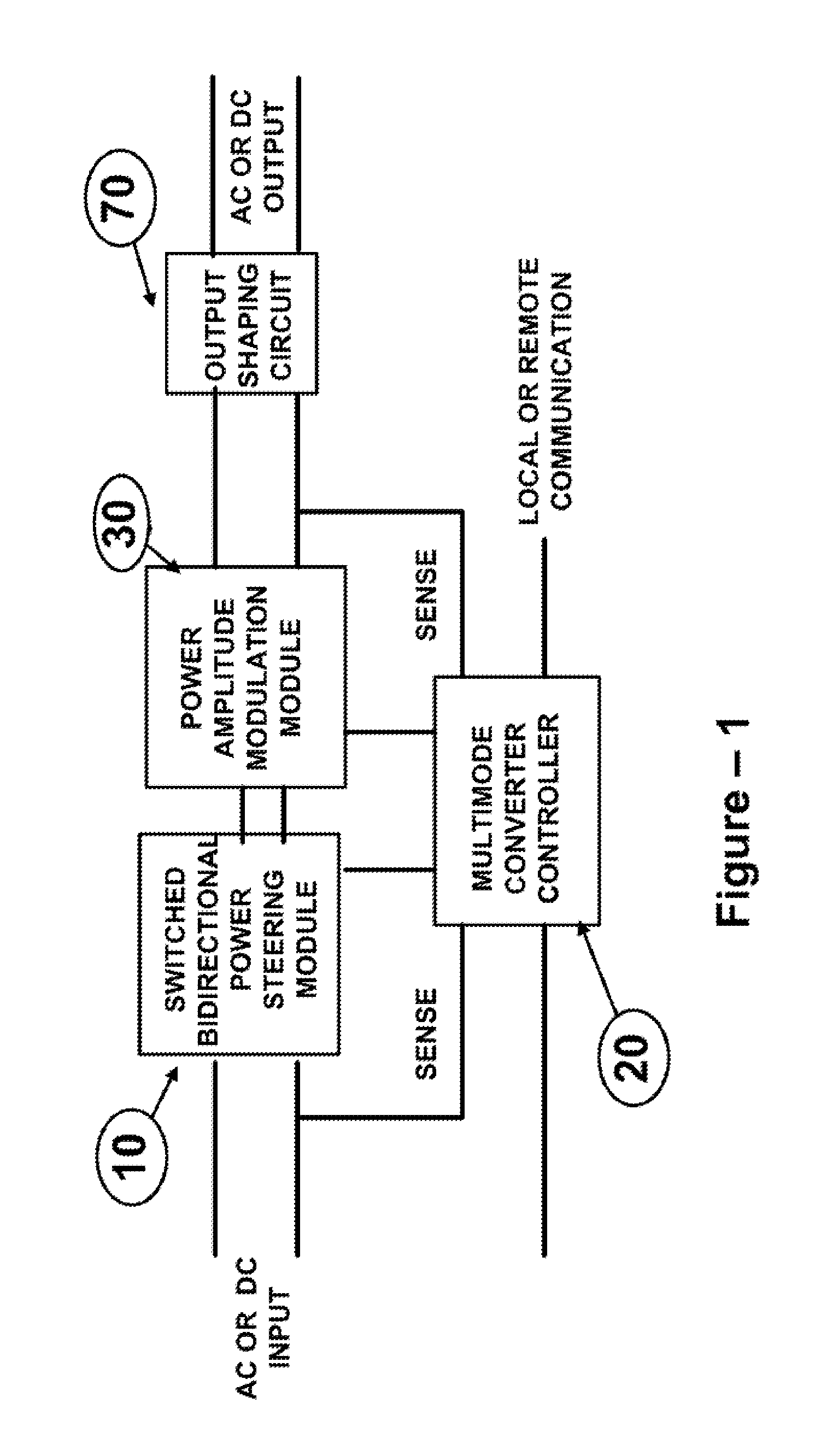
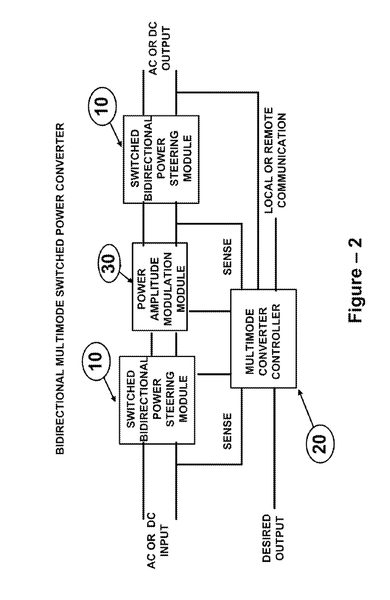
[0061]Various exemplary embodiments of the invention are shown in a modular fashion. The diagrams are not meant to be detailed schematics. However, each module, as shown in the diagrams, accurately depicts all of their operations, in detail. Circuit elements, such as those used to meet regulatory agency requirements are not shown. The modules with the same number are used in various drawings to show similar modes and operation. The mode and operations of the modules are shown using typical functional diagram and circuit components. The functions of any given module can be realized with other components than those that are illustrated in the figures. When multiple instances of the Multimode Switched Power Converter Modules are used, each instance of the same module can be realized with different circuit elements, within the scope of the invention.

[0062]The switch elements of the inventions, conduct positive, negative, and alternating polarity current when turned “ON” and block positi...


PUM


Abstract

The present invention is directed to Bidirectional Multimode Power Converter which employs a high frequency dynamically varying amplitude modulation and voltage steering method to convert the source AC or DC voltages to output AC or DC voltages, with programmable output voltage levels, output voltage frequency and duration. The inrush current control, turning off the idle converter, line voltage brown out protection, soft start, high pre-charge voltage generation, soft shut down of converter, dimming operation modes are inherent characteristics of the Bidirectional Multimode power converter. The Bidirectional Multimode Power Converters of the present invention facilitates bidirectional conversion and coupling multiple bidirectional sources and or loads.
The Bidirectional Multimode Power Converter of the present invention supports local and remote control for changing operational characteristics of the converter on demand or on a programmed time of the day for a specified duration of time.

Description

PRIORITY CLAIM[0001]The present invention claims priority to U.S. Provisional Application Ser. No. 61 / 439,367, filed Feb. 3, 2011, entitled “MULTIMODE SWITCHED POWER CONVERTER”, the disclosure of which is hereby incorporated by reference.FIELD OF THE INVENTION[0002]The present invention relates generally to bidirectional electric power conversion technology and in particular to a Multimode Switched Power Converter.BACKGROUND OF THE INVENTION[0003]Traditional source of electric power are fossil fuels plants, hydro electric and nuclear power plants. These plants serve many remote consumers using power transmission network or Power Grid. For efficient transmission of the power generated at the generating stations to the consumers, the power grid uses Alternate Current (AC) technology. Private residences, industrial complexes, streets, public buildings and other facilities use the AC power. The AC power generated in different countries has different line voltages and line frequencies.[0...

Claims


Application Information

Patent Timeline
IPC IPC(8): H02M11/00
CPCH02M1/10H02M3/33584H02M5/225Y02B70/1441H02M7/797H02M2007/4815H02M7/4807Y02B70/10H02M7/4815
Inventor SHARMA, VISWA N.
Owner SHARMA VISWA N
Why Eureka
Try Eureka