
Eureka
For R&D, Eureka makes reading and utilizing patents & technical documents easy.
Eureka AIR
Designed for self-driven R&D workflows. Generate viable solutions, solve complex R&D challenges, empower your innovation with AI.

Eureka Materials
Designed for material experts only. Revolutionize your material R&D, from search, analyze, to developing new materials.

TechResearch
Generate reliable direction feasibility study reports for your R&D in just a few steps.

TechSeek
Discover and master advanced knowledge NOW. Basics, ideas, possibilities, all at once.

TechMind
As an expert in R&D Theories, TechMind can generates customized viable solutions instantly.

TechRisk
Analyze your overall solution with one click, know your potential R&D risks in advance.

TechMonitor
Get weekly tech updates, stay abreast of the latest tech innovations and key insights.
Wireless communication method, base station, wireless communication system, and communication apparatus
- Summary
- Abstract
- Description
- Claims
- Application Information
AI Technical Summary
Benefits of technology
Problems solved by technology
Method used
Image

Examples
first embodiment
A. First Embodiment
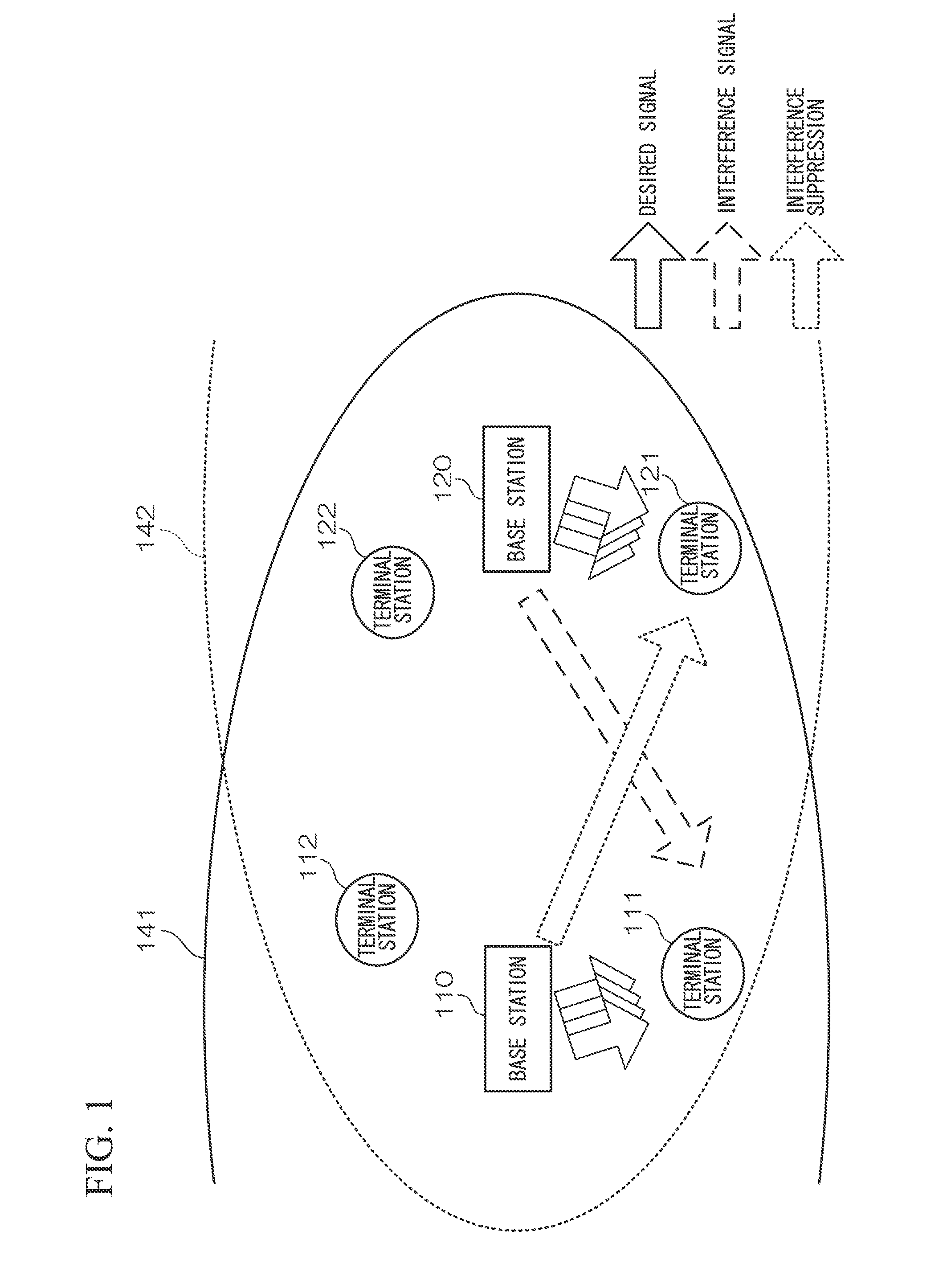
[0084]Next, a first embodiment of the present invention will be described. The first embodiment is characterized in that interference power for the terminal station 121 of the second communication cell is suppressed through transmission power control of the base station 110 of the first communication cell, and simultaneously, communication with the terminal station 111 of the first communication cell is performed to thereby increase a transmission capacity of the first communication cell 141.
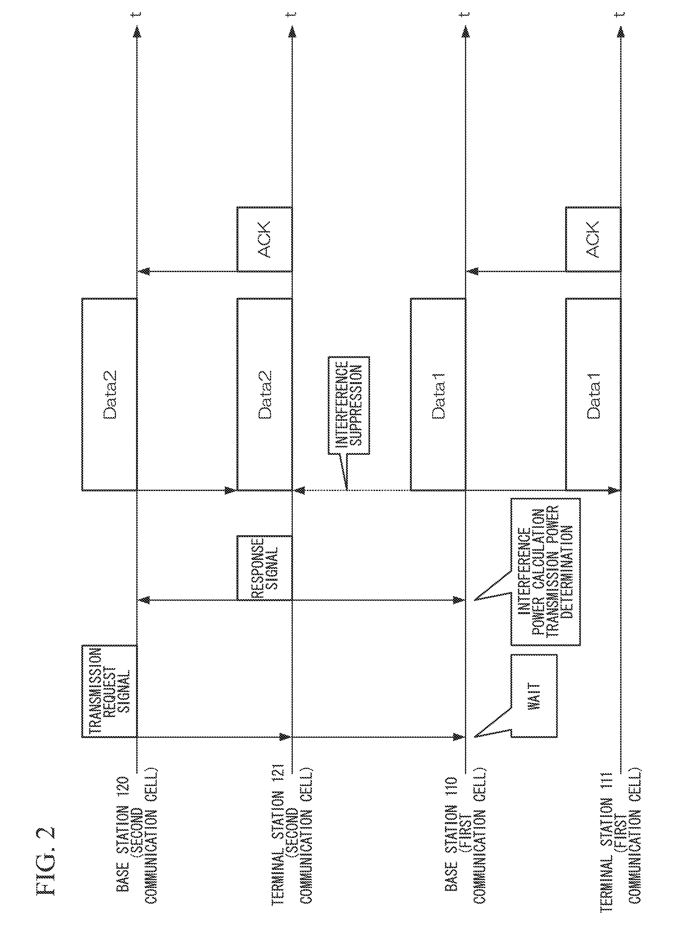
[0085]FIG. 2 is a sequence diagram illustrating a communication flow according to the first embodiment. In the first embodiment, the base station 120, the terminal station 121, the base station 110, and the terminal station 111 are included as shown in FIG. 1 and communication is performed according to the communication flow shown in FIG. 2.
[0086]In FIG. 2, first, the base station 120 transmits a transmission request signal to the terminal station 121.
[0087]The terminal statio...
second embodiment
B. Second Embodiment
[0097]Next, a second embodiment of the present invention will be described. The second embodiment is an example when the base station 120 of the second communication cell 142 performs transmission to the plurality of terminal stations 121 and 122 in the second communication cell 142. Accordingly, it is characterized in that a throughput of the first communication cell 141 increases even when the base station 120 of the second communication cell 142 performs transmission to the plurality of terminal stations 121 and 122.
[0098]FIG. 5 is a sequence diagram illustrating a communication flow according to the second embodiment. In the second embodiment, the base station 120, the terminal station 121, the terminal station 122, the base station 110, and the terminal station 111 are included as shown in FIG. 1, and communication is performed according to the communication flow shown in FIG. 5.
[0099]In FIG. 5, the base station 120 transmits a transmission request signal to...
third embodiment
C. Third Embodiment
[0104]Next, a third embodiment of the present invention will be described. The third embodiment is characterized in that an allowable interference power allowed to be given to the second communication cell 142 is set in advance, and the transmission power of the base station 120 is controlled to be equal to or less than the allowable interference power, thereby increasing a throughput of the first communication cell 141 above the first embodiment and the second embodiment.
[0105]In the third embodiment, the base station 120, the terminal station 121, the terminal station 122, the base station 110, and the terminal station 111 are included as shown in FIG. 1, and the communication is performed according to the communication flow shown in FIG. 2 or 5. However, the description of the third embodiment will be given with reference to FIG. 2. Further, the allowable interference power allowed to be given to the second communication cell 142 is detonated as Imax.
[0106]In t...
PUM
 Abstract
Description
Claims
Application Information
 - R&D Engineer
- R&D Manager
- IP Professional
- Industry Leading Data Capabilities
- Powerful AI technology
- Patent DNA Extraction
Browse by: Latest US Patents, China's latest patents, Technical Efficacy Thesaurus, Application Domain, Technology Topic, Popular Technical Reports.
© 2024 PatSnap. All rights reserved.Legal|Privacy policy|Modern Slavery Act Transparency Statement|Sitemap|About US| Contact US: help@patsnap.com