Battery terminal unit with current sensor

a terminal unit and current sensor technology, applied in the direction of cell components, coupling device connections, instruments, etc., can solve the problems of increasing the number of electric components of a vehicle, increasing the exhaustion of a vehicle-mounted battery, etc., to reduce the overhang from the battery edge, shorten the length to the extension part, and reduce the effect of overhang

Active Publication Date: 2013-02-14
YAZAKI CORP
View PDF15 Cites 16 Cited by
  • Summary
  • Abstract
  • Description
  • Claims
  • Application Information

AI Technical Summary

Benefits of technology

[0034]According to the above configuration, the connection part is offset with respect to an extension direction of the extension part (measured part), so that an overhang from the battery edge can be decreased. That is, while the overhang reaches “a bolt for fastening plus a current sensor body plus the connection part” as can be seen from FIG. 8 in a conventional unit, the overhang reaches only the longer dimension of “the current sensor body” or “the connection part” in the first invention.
[0035]Further, the magnetic detection element as the current sensor can be received and arranged in the inside, so that positioning to the extension part (measured part) can be performed by a simple structure and it is unnecessary to position and fix the current sensor (unit) to the bus bar.
[0036]According to the above configuration, the opposed walls are provided in the side opposite to the extension part in the attachment part, so that a length to the extension part can be shortened and the overhang can be decreased further.
[0037]According to the above configuration, shield means can be attached easily.
[0038]According to the above configuration, water drops failing from an upper portion of the sensor body flow out to the outside of the sensor body speedily, so that the shield plate does not corrode and therefore, the fear of causing an error in an output of the magnetic detection element is eliminated.

Problems solved by technology

Recently, kinds and the number of electric components of a vehicle have increased rapidly and exhaustion of a vehicle-mounted battery has become more intense.

Method used


Image

  • Battery terminal unit with current sensor
  • Battery terminal unit with current sensor
  • Battery terminal unit with current sensor

Examples


Embodiment Construction

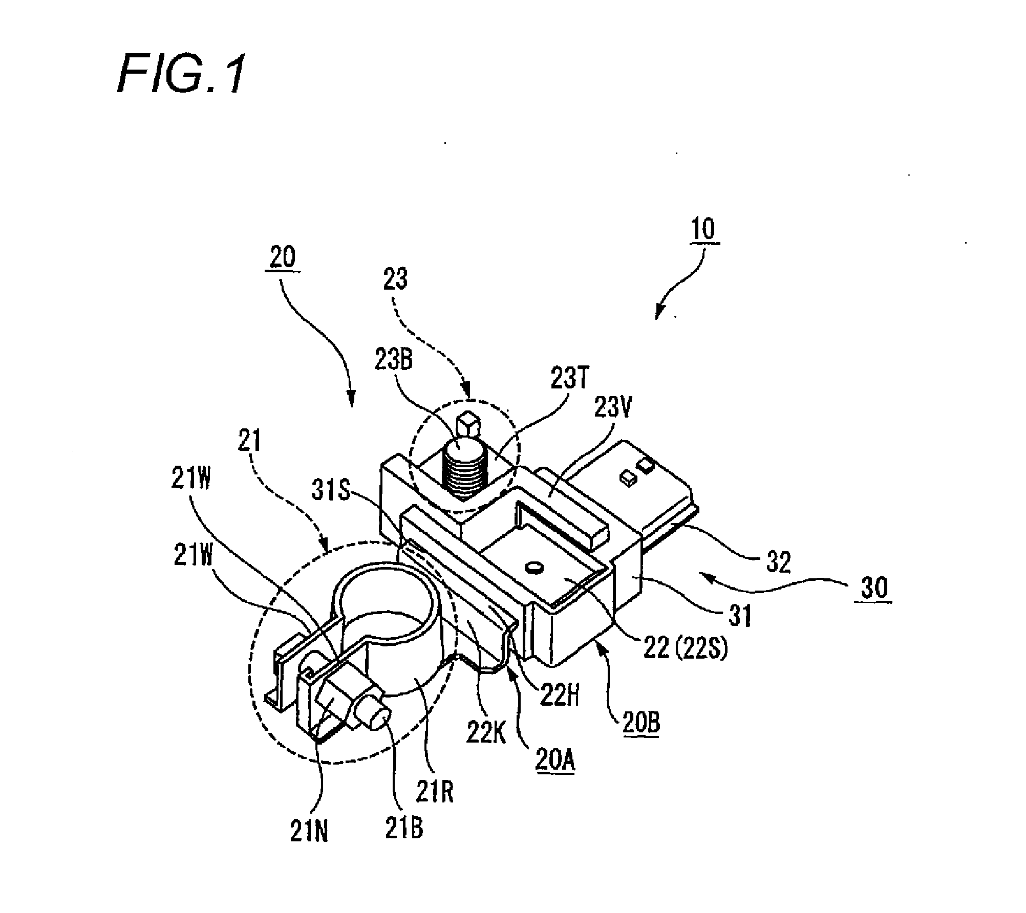
[0053]A battery terminal unit with a current sensor according to an embodiment, unnecessary to ensure large attachment space inside a vehicle engine room, will hereinafter be described based on the drawings.

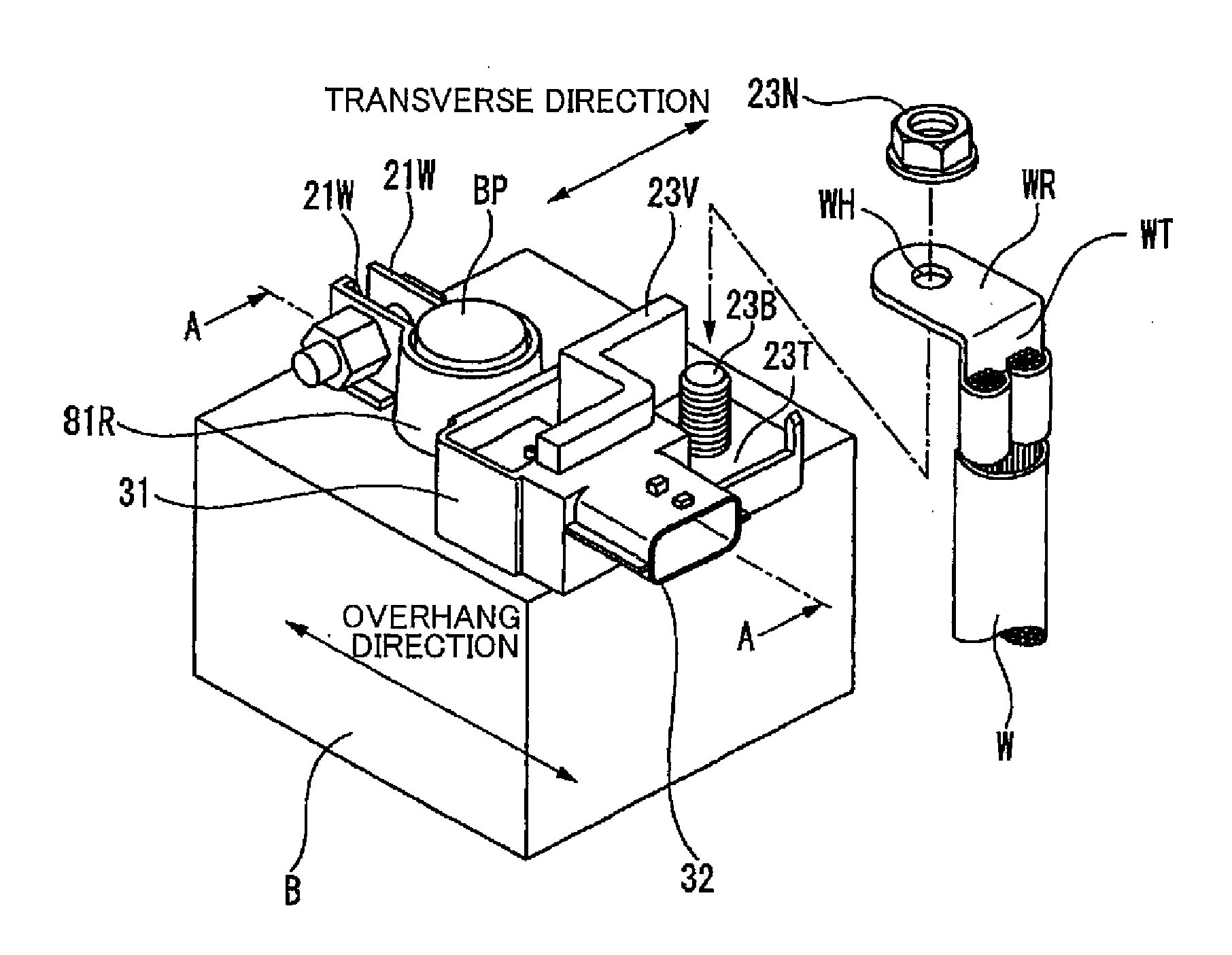
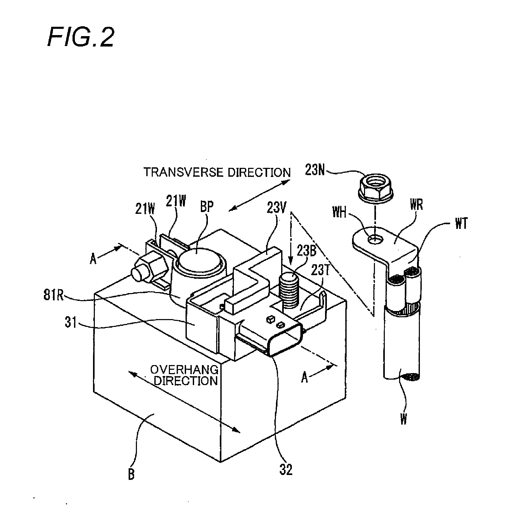
[0054]FIG. 1 is a perspective view showing a battery terminal unit with a current sensor according to the embodiment, and FIG. 2 is a perspective view showing a state of mounting the battery terminal unit with the current sensor of FIG. 1 on a battery post.

[0055]In FIG. 1, the battery terminal unit 10 with the current sensor has a battery mounting terminal 20 and the current sensor 30 attached to this battery mounting terminal 20.

[0056]This battery mounting terminal 20 and the current sensor 30 will hereinafter be described based on FIGS. 1 and 2.

20 According to the Embodiment>

[0057]In the battery mounting terminal 20 according to the embodiment, both of a bolt 23B for fixing a wire harness and a bus bar 20A (FIGS. 3 and 6) formed by bending are integrally formed by insert moldin...


PUM

PropertyMeasurementUnit
shapeaaaaaaaaaa
distanceaaaaaaaaaa
currentaaaaaaaaaa

Abstract

A battery terminal unit with a current sensor includes a bus bar for a battery terminal and a receiving portion. The bus bar includes an attachment part attached to a battery post, an extension part extended from the attachment part, and a connection part which continues to the extension part and is configured to connect a wire harness. The receiving portion receives a board on which a magnetic detection element is mounted so that the board is opposed to a surface of the extension part. The attachment part, the extension part and the connection part are integrally formed. The connection part continues to the extension part through an extending portion bent from the extension part so as to be positioned laterally to the extension part.

Description

TECHNICAL FIELD[0001]This invention relates to a battery terminal unit with a current sensor.BACKGROUND ART[0002]Recently, kinds and the number of electric components of a vehicle have increased rapidly and exhaustion of a vehicle-mounted battery has become more intense. As a result, there is a desire to monitor the remaining capacity of the battery. In such a case, a method for attaching a current sensor to a battery post and detecting a degree of exhaustion of the battery by magnitude of this current is proposed. In that case, the periphery of the battery post has no space sufficient to attach the current sensor and also, a touch in the case of attaching the current sensor to the side of a harness connected to the battery post may damage the sensor in consideration of attachment of the harness itself, and measures taken against this include a method for mounting a current sensor on a relay member coupled through fastening means capable of connecting and disconnecting both of a bat...

Claims


Application Information

Patent Timeline
Patent Type & Authority Applications(United States)
IPC IPC(8): H01M10/48H01M50/567H01M50/569
CPCH01M2/305H01M10/48G01R31/3696H01R13/6683H01R11/287G01R31/364Y02E60/10H01M50/567H01M50/569
Inventor HASHIO, SHINICHIMOCHIZUKI, TOSHIROU
Owner YAZAKI CORP
Why Eureka
Try Eureka