Structure of Power Socket

Inactive Publication Date: 2013-02-14
FANG YI HUI
View PDF2 Cites 27 Cited by
  • Summary
  • Abstract
  • Description
  • Claims
  • Application Information

AI Technical Summary

Benefits of technology

[0008]The primary objective of the present invention is to provide an improved structure of power socket, which could minimize the nu

Problems solved by technology

As shown in FIG. 2, said socket and electric switch are individually manufactured, and provided. with independent casings as well as electric parts and positive/negative terminals contained in the casings; hence, such devices must be manufactured. separately, resulting in higher material cost and time-consuming assembly; in particular, for the purpose of energizati

Method used


Image

  • Structure of Power Socket
  • Structure of Power Socket
  • Structure of Power Socket

Examples


Embodiment Construction

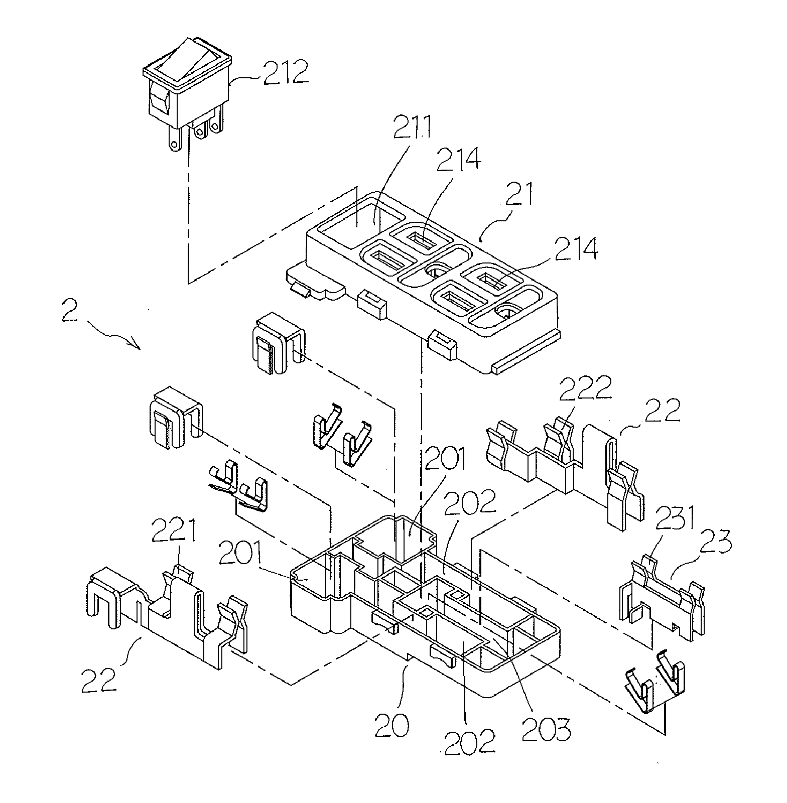
[0021]The improved power socket structure of a preferred embodiment of the present invention is illustrated in FIG. 3, wherein the power socket 2 comprising:

[0022]a T-shaped casing block 20, onto one surface of which two holding, grooves 201 are set correspondingly to its transverse direction, two caulking grooves 202 are set correspondingly to its longitudinal direction and a trough 203 is located, between two caulking grooves 202; onto the other surface of which three wire holes 204 are arranged correspondingly to two holding groove 201 and the trough 203;

[0023]a faceplate 21, mated with the casing block 20; onto one surface of which a holding space 211 containing electric switch 212 is set correspondingly to the transverse direction of T-shaped faceplate 21, and several slots 213 are set correspondingly to the longitudinal direction; onto the other surface of which at least one socket 214 is set in parallel; every socket includes neutral wire, live wire and earthing wire; moreove...


PUM


Abstract

An improved structure of power socket, which comprising: a casing block and a faceplate allowing to accommodate several power terminals, earthing terminals and electric switches, and the positive/negative contacts of power terminals, the contacts of earthing terminals and positive/negative contacts of electric switches are formed integrally at interval via a metal sheet, thus reducing substantially the number of spare parts and. facilitate the wiring; moreover, the faceplate is particularly made of transparent materials, allowing to visualize its interiors, improve the visual texture and sense of fashion, and also enhance the aesthetic feeling of indoor decorative environment; besides, the power socket can be applied to the faceplate of previous wall-mounted socket, enabling convenient replacement or assembly by the users, avoiding waste of resources and saving cost.

Description

BACKGROUND OF INVENTION[0001]1. Field of the Invention[0002]The present invention relates generally to a power socket, and more particularly to an improved one which allows to facilitate the assembly and reduce the cost by a simplified structure and transparent visual effect design of components.[0003]2. Description of Related Art[0004]As shown in FIG. 1, a wall-mounted common power socket 1 generally comprises: at least a socket 10 and an electric switch 11, of which the electric switch 11 could control the on / off state via the socket 10, thus improving the safety and preventing electric shock.[0005]As shown in FIG. 2, said socket and electric switch are individually manufactured, and provided. with independent casings as well as electric parts and positive / negative terminals contained in the casings; hence, such devices must be manufactured. separately, resulting in higher material cost and time-consuming assembly; in particular, for the purpose of energization, at least a branch ...

Claims


Application Information

Patent Timeline
IPC IPC(8): H01R13/70
CPCH01R2103/00H01R25/006H01R13/70
Inventor FANG, YI HUI
Owner FANG YI HUI
Why Eureka
Try Eureka