Crimp terminal, connection structural body and method for producing the crimp terminal

a technology of connection structure and crimp terminal, which is applied in the direction of coupling contact members, connections effected by permanent deformation, coatings, etc., can solve the problems of low potential aluminum corroded, galvanic corrosion, and the connection structure body cannot exhibit a sufficient conducting function, etc., to achieve no galvanic corrosion, high mass-productivity, and guarantee the effect of conducting function

Active Publication Date: 2013-02-14
FURUKAWA ELECTRIC CO LTD +1
View PDF5 Cites 34 Cited by
  • Summary
  • Abstract
  • Description
  • Claims
  • Application Information

AI Technical Summary

Benefits of technology

[0035]The present invention provides a crimp terminal, a connection structural body, and a method for producing the crimp terminal, which have a conducting function with certainty, with no galvanic corrosion occurring due to an electric wire and the terminal formed of different metal materials.
[0036]Also according to the present invention...

Problems solved by technology

However, an electrical structural body including an aluminum wire pressure-bonded to a crimp terminal has a problem that aluminum having a low potential is corroded as a result of contacting a metal material having a high potential, such as tin or gold used to plate the terminal, or such as a copper alloy used for forming the terminal; namely, has a problem of galvanic corrosion.
This causes a problem that the connection structural body cannot exhibit a sufficient conducting function.
However, the technology described in Patent Document 1 is difficult to be applied to the conventional processing procedure for producing a terminal, namely, a continuous procedure of punching out the material of the terminal with a press and bending the material.
Thus, it is difficult to mass-produce the terminal with the technology described in Patent Document 1.
In addition, the technology described in Patent Document has a problem that galvanic corrosion occurs due to the material used to form the elastic pi...

Method used


Image

  • Crimp terminal, connection structural body and method for producing the crimp terminal
  • Crimp terminal, connection structural body and method for producing the crimp terminal
  • Crimp terminal, connection structural body and method for producing the crimp terminal

Examples


example 1

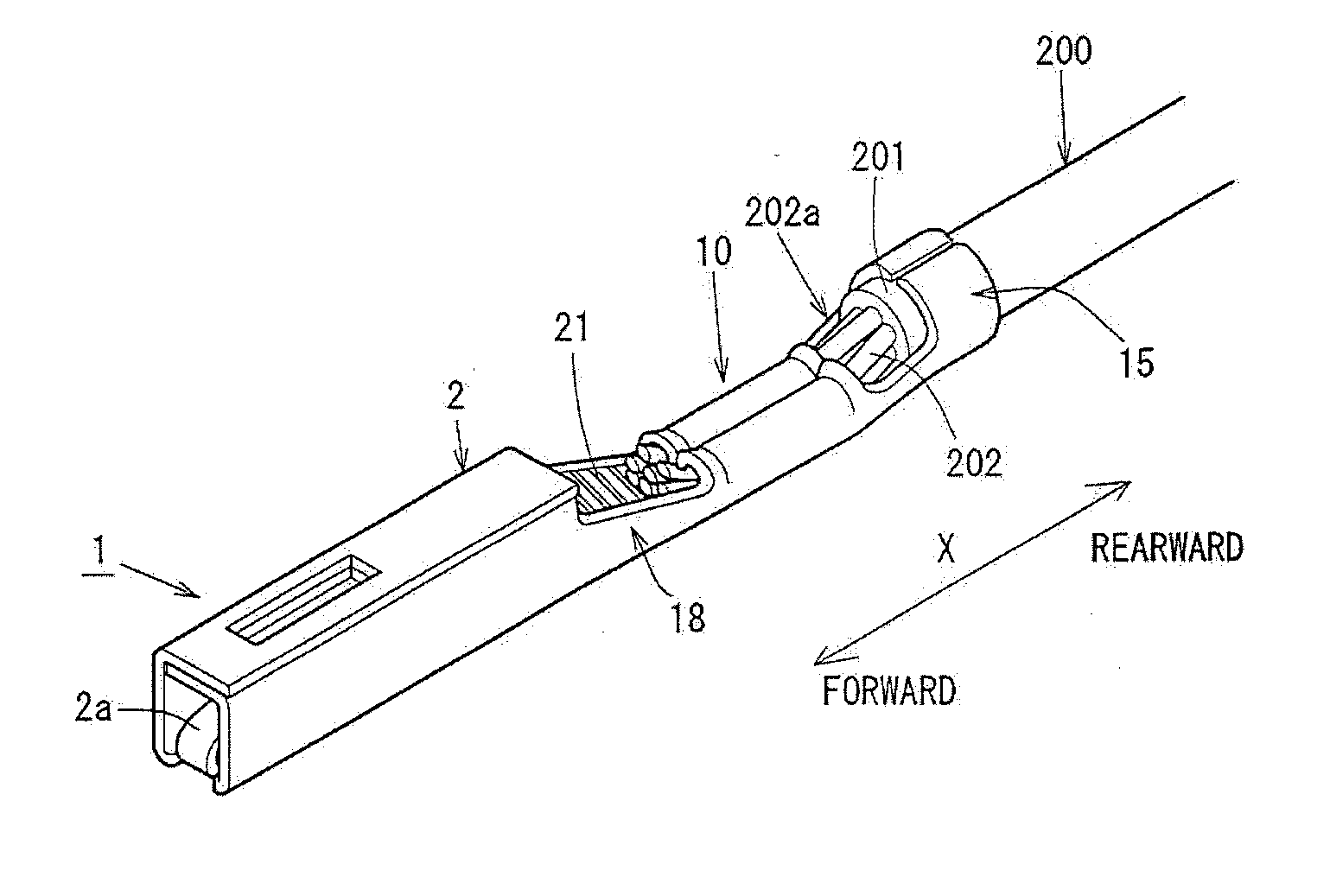
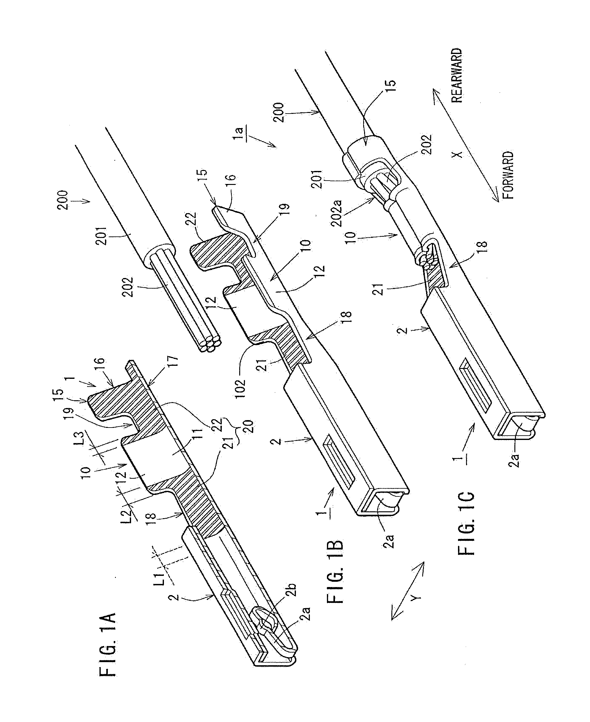
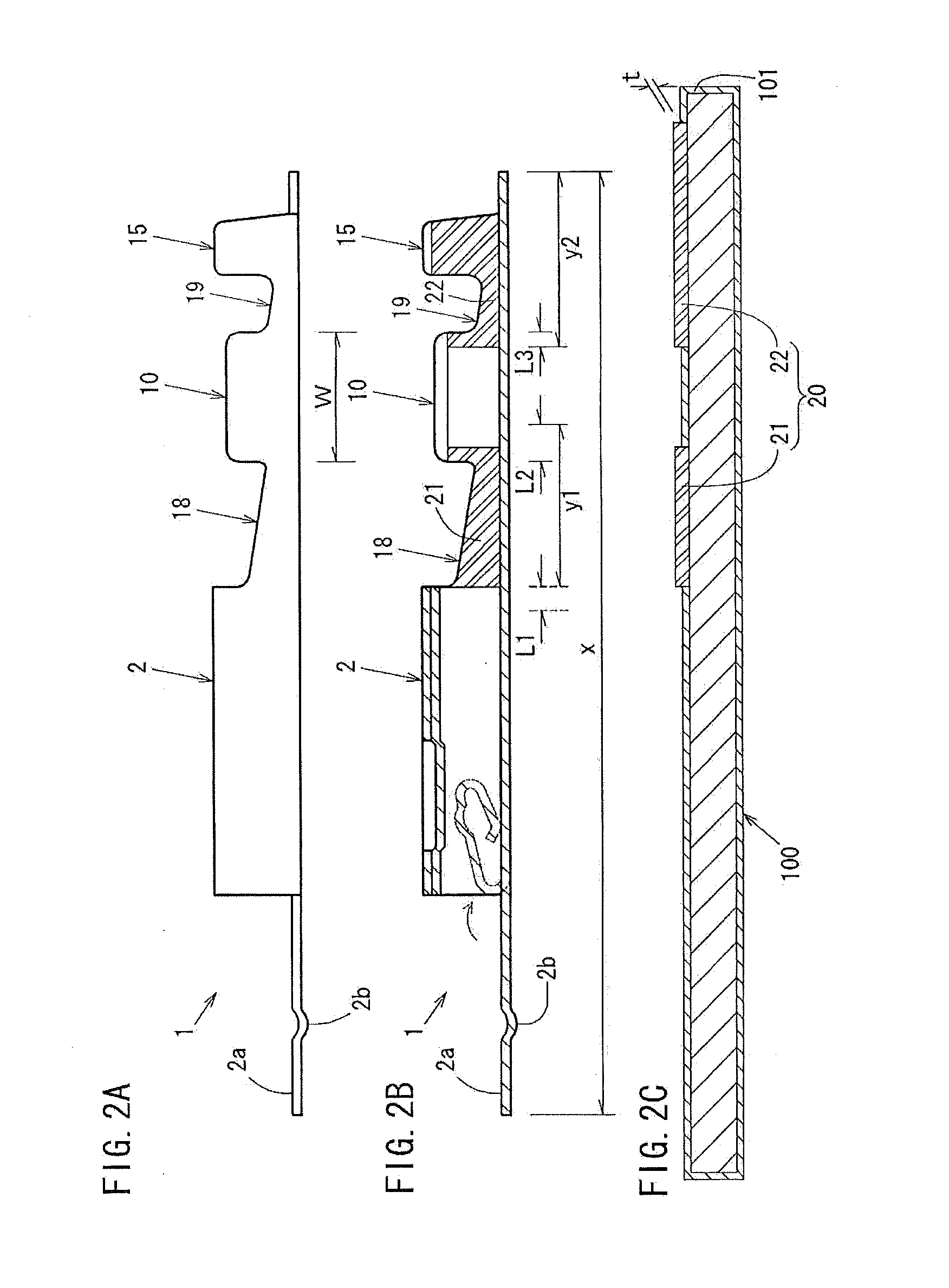
[0055]FIG. 1 provides isometric views of a crimp terminal 1 and a connection structural body 1a in a first pattern. FIG. 2 provides a side view and vertical cross-sectional views of the crimp terminal 1 in the first pattern. FIG. 3 shows a metal plate 100 in the first pattern. Similarly, FIGS. 4 through 6 show a second pattern. FIGS. 7 through 9 show a third pattern. FIGS. 10 through 12 show a fourth pattern.

[0056]FIGS. 1(a), 4(a), 7(a) and 10(a) are each an isometric view of the crimp terminal 1 which is cut off at a center thereof in a width direction. FIGS. 1(b), 4(b), 7(b) and 10(b) are each an isometric view of the crimp terminal 1 and an insulated wire 200 before being pressure-bonded to each other. FIGS. 1(c), 4(c), 7(c) and 10(c) are each an isometric view of the connection structural body 1a obtained as a result of pressure-bonding and thus connecting the crimp terminal 1 and the electric wire 200 to each other.

[0057]FIGS. 2(a), 5(a), 8(a) and 11(a) are each a side view of ...

example 2

[0120]A connection structural body 1b in this example includes exposed part resin cover sections 30 as shown in FIG. 13(a). The crimp terminal 1 including resin cover sections 20 and the core wires 202 formed of aluminum electric wires are pressure-bonded and thus connected to each other. In this state, exposed parts 202a (see FIG. 1(c)) of the core wires 202 are covered with a resin from above the first transition 18 and the second transition 19. Such covered parts are the exposed part resin cover sections 30.

[0121]The exposed part resin cover sections 30 are formed as follows. The insulated wire 200 is pressure-bonded by the insulation barrel section 15. Then, a photocurable resin is applied so as to cover the exposed parts 202a, and irradiated with ultraviolet rays to be cured.

[0122]Owing to this, the effect of preventing galvanic corrosion while guaranteeing the conducting performance of the connection structural body 1b can be improved.

[0123]An effect confirming test was perfor...

example 3

[0128]An end surface-covered crimp terminal 1′ in this example includes, as shown in FIG. 13(b), the resin cover sections 20 (21, 22) at prescribed positions and end surface resin cover sections 40 for covering end surfaces 102 of parts of the crimp terminal 1 where the resin cover sections 20 are provided. In FIG. 13(b), the crimp terminal 1 (see FIG. 1) includes the first resin cover section 21 and the second resin cover section 22 formed on the inner surfaces of the first transition 18 and the second transition 19, and the end surface resin cover sections 40 are formed on the end surfaces 102 of the parts of the crimp terminal 1 where the resin cover sections 20 are provided. However, the end surface resin cover sections 40 are not limited to this. For example, the end surface resin cover sections 40 may be formed on end surfaces 102 of the crimp terminal 1 including the third resin cover section 23 in addition to the first resin cover section 21 and the second resin cover sectio...


PUM


Abstract

Has an object of providing a crimp terminal, a connection structural body, and a method for producing the crimp terminal, which has a conducting function with certainty, with no galvanic corrosion occurring due to an electric wire and the terminal formed of different metal materials. A crimp terminal 1 includes a box section, and a pressure-bonding section including a wire barrel section and an insulation barrel section, which are provided in this order. The crimp terminal is formed of a metal plate which is formed of a copper alloy having a higher potential than aluminum used to form core wires of an insulated wire which is to be pressure-bonded by the pressure-bonding section. The crimp terminal 1 includes, in at least a part thereof, a resin cover section for covering a surface of the metal plate with a resin.

Description

TECHNICAL FIELD[0001]The present invention relates to a crimp terminal attachable to, for example, a connector or the like for connection of a wire harness for an automobile, and a connection structural body including the same; and in more detail, to a crimp terminal connectable to a wire harness formed of an aluminum conductor or an aluminum alloy conductor, and a connection structural body including the same.BACKGROUND ART[0002]Today, carbon dioxide emissions from automobiles are required to be reduced. Since reduction of weight of vehicles greatly influences improvement of fuel efficiency, the weight of wire harnesses for connecting electrical components are also required to be reduced. Therefore, it has been studied to, for example, replace copper-based materials which are conventionally used for electric wires or the like used for the wire harnesses with aluminum, and aluminum has been used for some electric wires.[0003]However, an electrical structural body including an alumin...

Claims


Application Information

Patent Timeline
IPC IPC(8): H01R4/10B05D1/36B05D5/12
CPCH01R4/185H01R4/62H01R43/16H01R13/11H01R13/03
Inventor MITOSE, KENGOKAWAMURA, YUKIHIRO
Owner FURUKAWA ELECTRIC CO LTD
Why Eureka
Try Eureka