Connection structural body

a technology of connecting structure and structural body, which is applied in the direction of connection contact material, permanent deformation-induced connections, electrical devices, etc., can solve the problems of corroding, dissolved or extinguished terminal sections, preventing the conductivity function of electric wires from being sufficient, and not being water-proof, so as to prevent galvanic corrosion, reduce production costs, and reduce production costs

Active Publication Date: 2013-02-14
FURUKAWA ELECTRIC CO LTD +1
View PDF26 Cites 21 Cited by
  • Summary
  • Abstract
  • Description
  • Claims
  • Application Information

AI Technical Summary

Benefits of technology

[0038]The present invention provides a connection structural body in which an electric wire and a crimp terminal formed of different metal material are connected to each other, and which is produced at low cost and with a small number of production steps, prevents galvanic corrosion, and has a conducting function with certainty.

Problems solved by technology

Due to the galvanic corrosion, the aluminum electric wire pressure-bonded by a pressure-bonding section of the terminal is corroded, dissolved or extinguished.
This raises the electric resistance, and may prevent the electric wire from having a sufficient conducting function.
However, in the connection structure described in Patent Document 1, a part of the aluminum electric wire from a tip of the insulating cover to a position at which the electric wire is inserted into the terminal is exposed and is not water-proof.
Therefore, in the case where the crimp terminal is formed of brass, copper or the like, which is used conventionally, or in the case where there is solder, galvanic corrosion is likely to occur in the contact part of the aluminum electric wire and the crimp terminal or the soldered part of the aluminum electric wire due to difference in the ionization tendency of the materials.
However, the connection structure described in Patent Document 2 is for use in thick electric wires such as, for example, electric wires for electric power used for electric automobiles, and is difficult to be applied to thin electric wires.
This connection structure also requires many components such as special members, an intermediate cap of a specific shape, elastic members and the like, and the work of inserting the components is complicated.
For these reasons, the connection structure described in Patent Document 2 is disadvantageous in terms of cost.

Method used


Image

  • Connection structural body
  • Connection structural body
  • Connection structural body

Examples


Embodiment Construction

[0047]An embodiment of the present invention will be described with reference to the drawings.

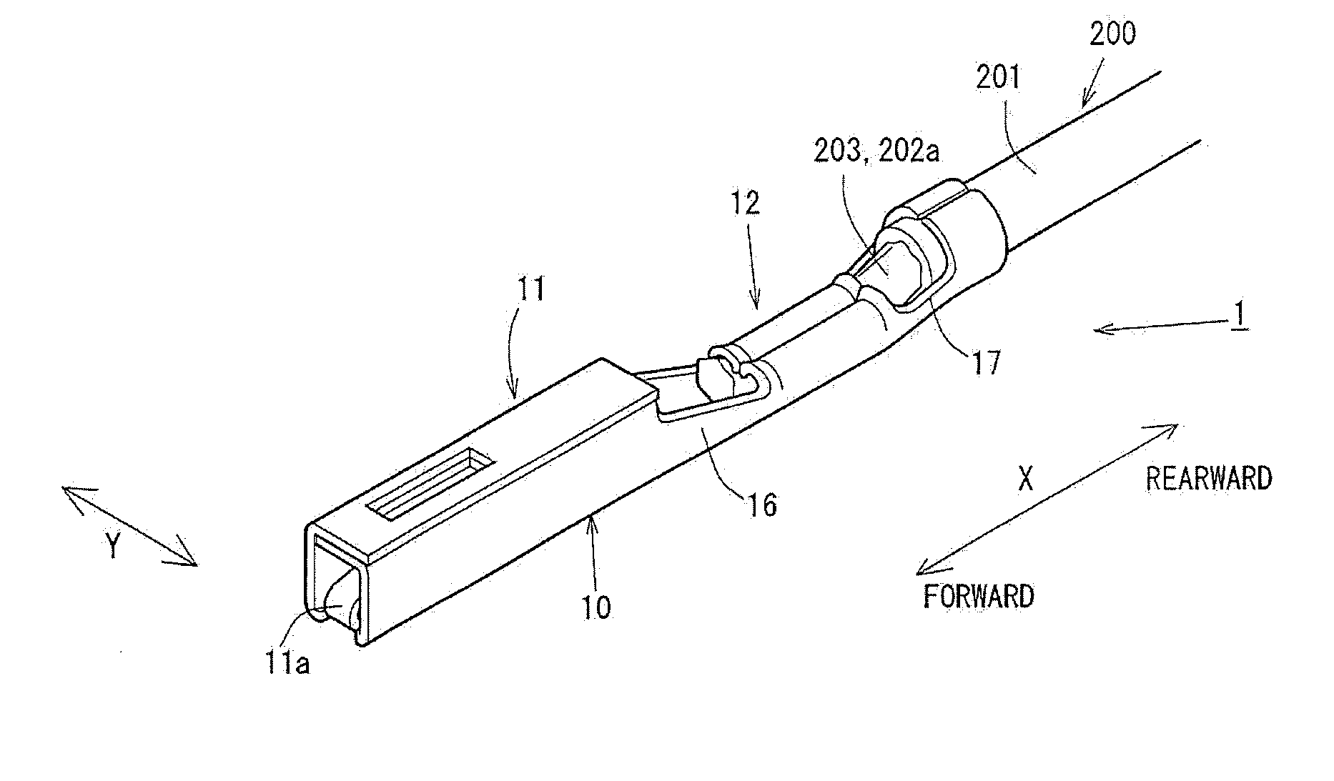
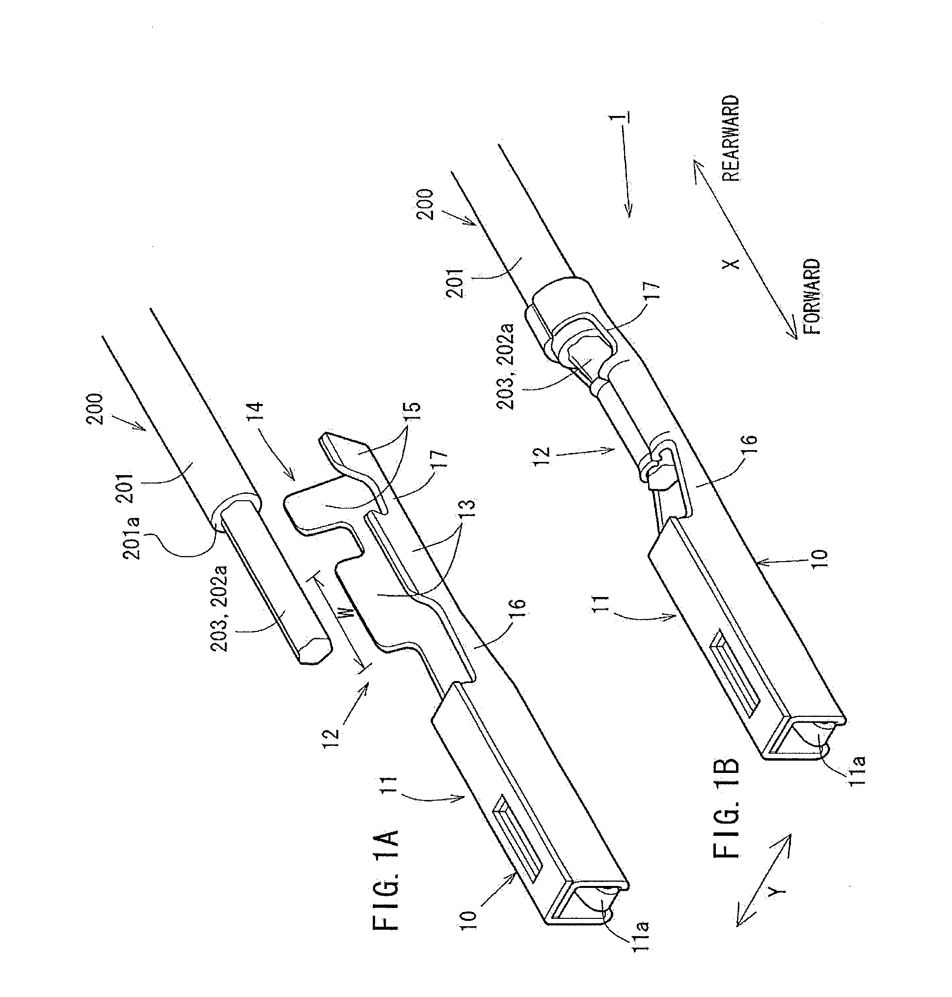
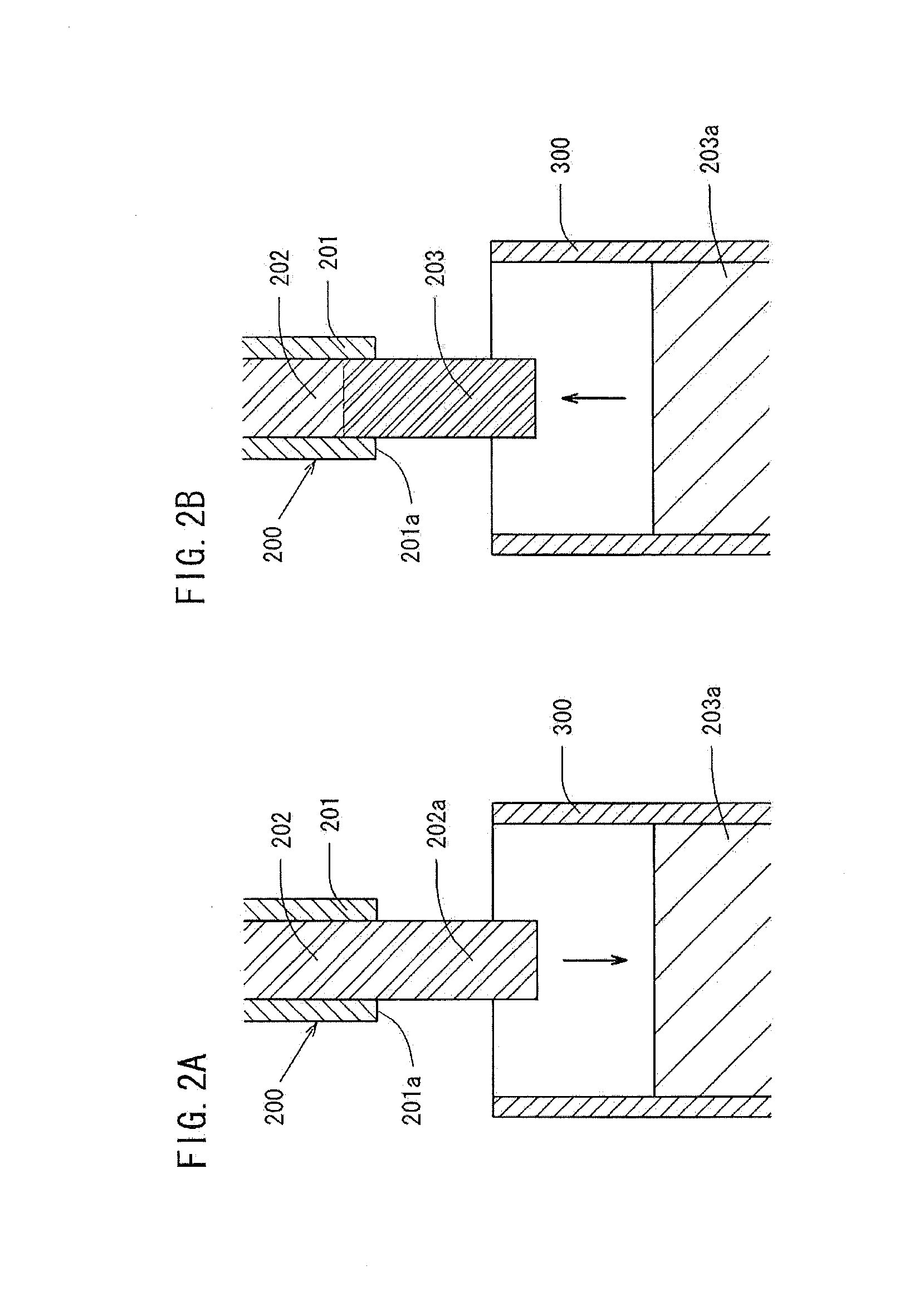
[0048]FIG. 1 shows a crimp terminal 10 and a connection structural body 1 in a first pattern. FIG. 2 shows a covering method using solder for the first pattern. FIG. 2(a) shows a state before a tip part of an insulating cover 201 is stripped off and an aluminum electric wire tip part 202a is immersed in molten solder 203a in a solder bath 300. FIG. 2(b) shows a state where the aluminum electric wire tip part 202a is immersed in the molten solder 203a in the solder bath 300 and is covered with cover solder 203.

[0049]FIG. 3 shows a crimp terminal 10 and a connection structural body 1 in a second pattern. FIG. 4 shows a covering method using solder for the second pattern. FIG. 4(a) shows a state before a tip part of the insulating cover 201 is stripped off and the aluminum electric wire tip part 202a is immersed in the molten solder 203a in the solder bath 300. FIG. 4(b) shows a state where th...


PUM


Abstract

In a connection structural body, an aluminum electric wire tip part and a crimp terminal are connected to each other. The aluminum electric wire tip part is an exposed tip part of an insulated wire including an aluminum core wire and an insulating cover for covering the aluminum core wire. The crimp terminal includes a wire barrel section for pressure-bonding and thus connecting the aluminum electric wire tip part and is formed of a metal material having a higher potential than that of the aluminum core wire. The aluminum electric wire tip part is covered with a cover solder and / or a cover resin, pressure-bonded, and connected to the wire barrel section such that the aluminum electric wire tip part is covered with the cover and / or the cover resins, with no gap, from an insulating cover tip part to a rear end portion of the wire barrel section.

Description

TECHNICAL FIELD[0001]The present invention relates to a connection structural body using a crimp terminal attachable to, for example, a connector or the like for connection of a wire harness for an automobile; and in more detail, a connection structural body in which a wire harness formed of an aluminum electric wire or an aluminum alloy electric wire is connected to a crimp terminal.BACKGROUND ART[0002]Conventionally, for gasoline automobiles, a wire harness (or a battery cable) or the like for pressure-bonding and thus connecting a tin-plated copper terminal and a copper electric wire to each other is used. Since carbon dioxide emissions from automobiles are required to be reduced today, electric automobiles or hybrid automobiles using more wire harnesses than the gasoline automobiles are in a wider use.[0003]For all the types of automobiles including gasoline automobiles, weight reduction of a vehicle significantly influences the fuel efficiency. In an attempt to reduce the weigh...

Claims


Application Information

Patent Timeline
Patent Type & Authority Applications(United States)
IPC IPC(8): H01R4/10
CPCH01R4/024H01R4/62H01R4/187H01R4/185
Inventor TAKASHIMA, NAOYAMITOSE, KENGOKAWAMURA, YUKIHIRO
Owner FURUKAWA ELECTRIC CO LTD
Why Eureka
Try Eureka