Probe and system for use with an ultrasound device
a technology for ultrasound devices and probes, applied in the field of probes and systems for use with ultrasound devices, can solve the problems of delay in delivery of life-saving fluids or medications, neither simple nor risk-free procedures, and the risk of unsuccessful placement of probes
- Summary
- Abstract
- Description
- Claims
- Application Information
AI Technical Summary
Benefits of technology
Problems solved by technology
Method used
Image
Examples
example 1
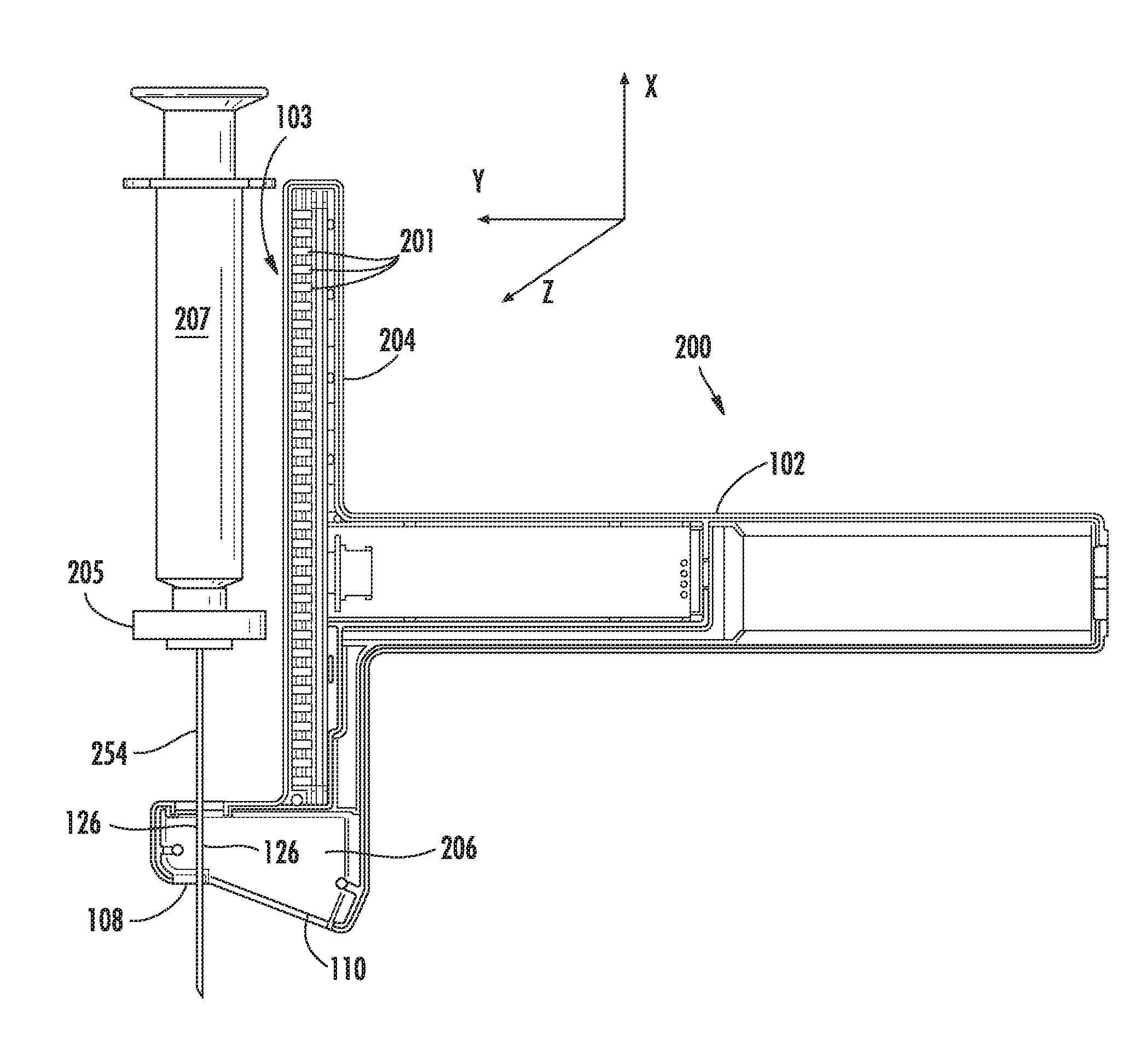
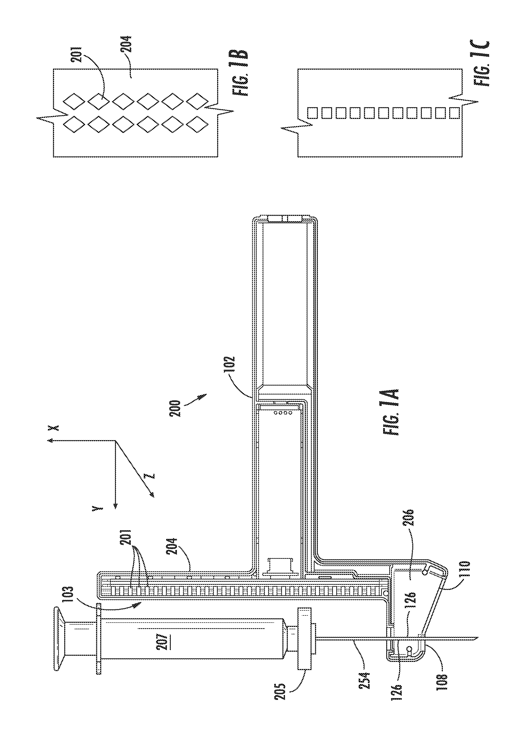
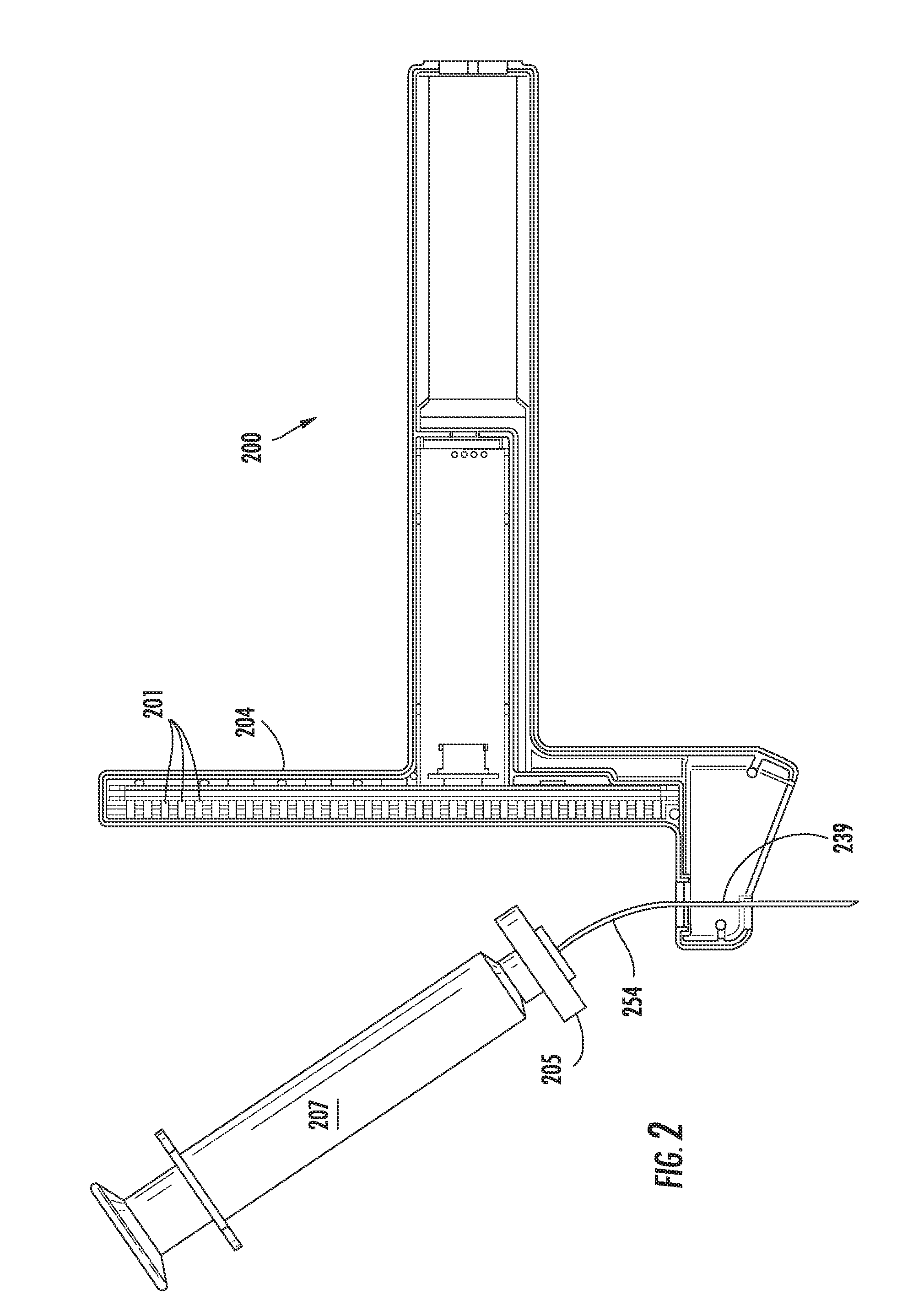
[0135]An ultrasound device as illustrated in FIG. 13 was utilized. The needle probe 254 was flexed away from the post 204 of the device, as shown. A sensor array 103 of Hall effect sensors was located within the post 204. The sensors used were ratiometric linear Hall effect sensors available from Allegro MicroSystems, Inc., model no. A1321. FIG. 13 also provides a top view 270 of the post 204, showing the curvature of the post to accommodate the target magnet 205. The needle 254 was flexed by increasing levels away from the post 204. Sensor array readings, SH, which can be converted to a location parameter by simple geometric conversion based upon the ultrasound device, are provided in the Table 1, below. Data in each row were obtained with the same fixed position of the needle.
TABLE 1Level H012345678910111213141516Meter702.5699696692689Readings611608605602599596594SH520517514511509507506504502500499497496460458455453451449447446444443442441440439437401399397394393391389386384383381...
example 2
[0143]FIG. 14 illustrates a geometric model utilized to describe the tilt of a target magnet with the flexing of an attached probe from alignment with a probe guide. An assumption was made that the needle was bent with a constant radius of R. (In this example, the value for the level index, H, has been converted to the distance from the sensor array to the magnet.) The following equations can be written:
LB=R*α
h=2R*sin2(α / 2)
h+RM=H+RM*cos(α)
[0144]RM is the magnet radius (11 mm in this example).
[0145]Thus,
H=[LB*sin2(α / 2)] / α−RM*cos(α)
[0146]This equation was solved digitally, and the results for the values of a (in radians) are shown in Table 2, below.
TABLE 2HLB =LB =LB =LB =LB =(mm)68 mm58 mm48 mm38 mm28 mm0000003.53.343.94.685.847.765.56.67.79.2211.4414.927.59.8411.4413.6416.7821.649.513.0415.1417.9621.962811.516.218.7622.227.0213.519.3422.3426.38
[0147]The results of Examples 1 and 2 were combined to provide a graph (FIG. 15) illustrating the experimentally obtained values for the shif...
example 3
[0148]A second set of data for SH, the output of the Hall effect sensor array, were obtained utilizing a system similar to that described above in Example 1. Raw data is provided below in Table 3. Best fit of the data provided values of the correlation factors a=−0.051 and b=4.26. Thus, the correlation equations are as follows (the values for Soffs and SH are in units of 0.1 mm, hence the conversion factor in the equation):
LB=(Soffs−SH) / 10−LC,
S0=SH+(4.26−0.051·LB)·H,
TABLE 3HLB =LB =LB =LB =LB =(mm)68 mm58 mm48 mm38 mm28 mm0203306404501597.53.51992963974935885.5196293.53844865817.5194289.53804745659.5192285.537647055811.5189281.537346413.5184276.5371
[0149]Utilizing these correlation factors in the processing software, a test was run. A needle of length 88.9 mm (3.5 inches) was used. A value of Soffs was determined to be 685. A value of LC was determined to be 20.9 mm.
[0150]A device as illustrated in FIG. 13 including a detector was used. The detector provided the following readings:
[...
PUM
 Abstract
Description
Claims
Application Information
 - R&D
- Intellectual Property
- Life Sciences
- Materials
- Tech Scout
- Unparalleled Data Quality
- Higher Quality Content
- 60% Fewer Hallucinations
Browse by: Latest US Patents, China's latest patents, Technical Efficacy Thesaurus, Application Domain, Technology Topic, Popular Technical Reports.
© 2025 PatSnap. All rights reserved.Legal|Privacy policy|Modern Slavery Act Transparency Statement|Sitemap|About US| Contact US: help@patsnap.com


