Optical tracking vehicle control system and method

a technology of optical tracking and control system, applied in the field of control system, can solve the problems of difficult steering of the vehicle, computationally expensive and difficult to implement in practice, and the controller does not “know” where the vehicle is actually located in space, so as to improve the control performance and accelerate the computation

Active Publication Date: 2013-02-14
AGJUNCTION
View PDF35 Cites 85 Cited by
  • Summary
  • Abstract
  • Description
  • Claims
  • Application Information

AI Technical Summary

Benefits of technology

[0077]Properties of the spatial hash-key algorithm may include: points which are close to each other in the real world should have closely related hash keys (i.e. the algorithm should maintain “locality”), the algorithm should operate using whatever coordinate system the control system uses to represent the region, the algorithm should be adapted for digital implementation (hence, it should be adapted to operate using integer or floating-point numbers, preferably with 64-bit “double” precision or better) the algorithm should be fast to compute.
[0078]It is explained above that the control system of the present invention, and ideally the spatial database, may be adapted to receive updated data from the controller and/or an external source. The spatial database can be adapted to receive the updated information at control speed. Data received from the controller may include or may be used to generate, for example, estimates of the vehicle's predicted state (i.e. its speed, position, orientation,...

Problems solved by technology

A problem with previous vehicle control systems is that they are inherently “one-dimensional” or “linear” in nature.
However, the controller does not “know” where the vehicle is actually located in space.
This calculation can be computationally expensive and difficult to implement in practice, particularly for curved, piecewise, broken or other complex path trajectories.
However, with most existing control systems, the controller is only able to control the steering of the vehicle as it proceeds along each of the swaths.
It is much harder to control the steering of the vehicle as it turns around between one swath and the next.
However, at a fundamental level, the control system does not inherently know where the vehicle is consequently located in space or the spatial relationship between each swath.
The “one-dimensional” or “linear” nature of existing control systems also causes other difficulties.
However, as current control systems only recognize where the vehicle is located along the path, not where the vehicle is actually located in space, the control system itself is therefore unable to recognize whether the location of the obstacle coincides with the trajectory of the path, and hence whether there may be a collision.
This multi-modular control system structure is complicated and can lead to computational inefficiencies because the different modules may each perform many of the same geometric calculations for their own respective purposes, separately from one another, leading to “doubling up” and unnecessary computation.
Also, with this modular control system structure, control of the vehicle generally passes from one module to another as described above, but determining when one module should take over from another creates significant difficulties in terms of both system implementation and maintenance.
Another problem associated...

Method used


Image

  • Optical tracking vehicle control system and method
  • Optical tracking vehicle control system and method
  • Optical tracking vehicle control system and method

Examples


Embodiment Construction

[0109]1. Introduction and Environment

[0110]As required, detailed embodiments of the present invention are disclosed herein; however, it is to be understood that the disclosed embodiments are merely exemplary of the invention, which may be embodied in various forms. Therefore, specific structural and functional details disclosed herein are not to be interpreted as limiting, but merely as a basis for the claims and as a representative basis for teaching one skilled in the art to variously employ the present invention in virtually any appropriately detailed structure.

[0111]Certain terminology will be used in the following description for convenience in reference only and will not be limiting. For example, up, down, front, back, right and left refer to the invention as oriented in the view being referred to. The words “inwardly” and “outwardly” refer to directions toward and away from, respectively, the geometric center of the embodiment being described and designated parts thereof. Glo...


PUM


Abstract

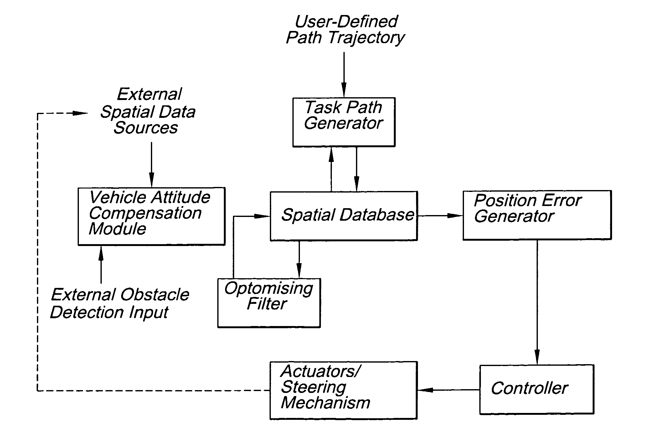
A vehicle control system having a controller and a spatial database adapted to provide spatial data to the controller at control speed. The spatial data provided from the spatial database to the controller includes images collected from an optical sensor subsystem in addition to other data collected by a variety of sensor types, including a GNSS or inertial measurement system. The spatial data received by the controller from the database forms at least part of the control inputs that the controller operates on to control the vehicle. The advantage provided by the present invention allows control system to “think” directly in terms of spatial location. A vehicle control system in accordance with one particular embodiment of the invention comprises a task path generator, a spatial database, at least one external spatial data receiver, a vehicle attitude compensation module, a position error generator, a controller, and actuators to control the vehicle.

Description

CROSS-REFERENCE TO RELATED APPLICATION[0001]This application is a continuation-in-part of and claims the benefit of U.S. patent application Ser. No. 12 / 504,779, filed Jul. 17, 2009, and is a continuation-in-part of and claims the benefit of U.S. patent application Ser. No. 12 / 947,620, filed Nov. 16, 2010, which is continuation of and claims the benefit of U.S. patent application Ser. No. 11 / 620,388, filed Jan. 5, 2007, entitled “Vehicle Control System,” now U.S. Pat. No. 7,835,832, issued Nov. 16, 2010, which are all incorporated herein by reference.BACKGROUND OF THE INVENTION[0002]1. Field of the Invention[0003]The present invention relates to a control system for controlling the direction of travel of a vehicle, and in particular to a control system having an embedded spatial database using optical tracking for vehicle control and guidance. The control system of the present invention may also be used to control other aspects of a vehicle's motion, such as speed or acceleration. Fu...

Claims


Application Information

Patent Timeline
IPC IPC(8): G05D1/02
CPCB62D15/025G01S19/43G05D1/0253G05D2201/0201G05D1/0272G05D1/0278G05D1/027G05D1/0231G05D1/0274
Inventor REEVE, DAVID R.MACDONALD, ANDREW JOHNMORRISON, CAMPBELL ROBERT
Owner AGJUNCTION
Why Eureka
Try Eureka