Electromechanical assembly for connecting a series of guns used in the perforation of wells

a technology of electromechanical assembly and perforation well, which is applied in the direction of drilling machine and method, drilling accessories, fluid removal, etc., can solve the problems of increasing the likelihood that operators may commit errors, and achieve the effect of preventing cable failur

Active Publication Date: 2013-02-21
TASSAROLI
View PDF4 Cites 71 Cited by
  • Summary
  • Abstract
  • Description
  • Claims
  • Application Information

AI Technical Summary

Benefits of technology

[0011]Providing a system for connecting wires with a clip which design permits the arming and assembly of the perforating guns without the possibility of error, which can cause failures in the operation and generate large economic losses, and / or may cause unfortunate accidents.
[0012]Being able to wire the assembly by using said clips makes wiring an easier task and requires less time, meaning less time with personnel working with explosive material.
[0013]As a security improvement, the detonators utilized in the gun assembly remain short-circuited and grounded until the preceding gun is detonated; only in that moment, is the detonator connected to the live electric line which stretches the entire length of the carrier allowing for the conduction of the detonating charge; however, a diode prevents the detonator from firing from a charge of the same polarity as the gun previously fired: to detonate, one must change the polarity of the charge. This implementation of this improvement increases security while working with explosives.
[0014]A pressure activated electromechanical changeover switch. The switch has a conductive dart, which is activated at a predetermined pressure set by a mechanical fuse in the shape of an expendable ring that breaks under stress from the explosion. On receiving the impact produced by the explosion of the shaped charges located in the charge carriers of the lowest active gun in the gun assembly, the dart breaks the mechanical fuse and trips the switch. The dart acts as a switch between contacts that are exposed in the housing of the apparatus and releases the detonator from short-circuit and ground, connecting the detonator of the gun immediately above the fired gun to the circuit. This allows said detonator to later receive the electronic tension, albeit with opposing polarity to the previous gun. This switch, while it is in its initial position, in repose, before moving, allows the electrical charge, positive or negative, to reach the bottom gun and maintains the remaining and unfired portion of the gun assembly short-circuited and grounded.
[0015]Each charge carrier is limited to two insulating and centralizing end plates: the bottom with a central orifice through which the firing line and the unit ground to a tab located on the outer edge of the end plate pass, placing the unit ground in contact with the outer shell of the gun, that acts as the ground for the entire gun assembly (bottom end plate without retractable contact pin), both cables are tied to a connector; and the top end plate that has a spring-loaded electrical contact pin which function is, on one hand, to assure constant electrical contact with the preceding switch, in spite of variances in lengths that can be produced, and on the other, prevent failure of the cables that connect the guns due to twisting, as frequently occurs with current practices. The bottom plate without said pin, functions to connect the ground to the gun assembly, and to space and centralize the charge carrier within the gun. Both end plates serve to protect the elements that form the series of guns (top sub, tandem sub, and bottom sub) from fragments produced by the explosion, in such a way that these parts may be used again.

Problems solved by technology

Hours are controlled by working against the clock and by penalizing setbacks; to that respect, it is absolutely necessary that the strictest safety norms be followed while handling explosive material; all of these factors together contribute to an increased likelihood that operators may commit errors while wiring or assembling the perforating guns to be introduced into the well.

Method used


Image

  • Electromechanical assembly for connecting a series of guns used in the perforation of wells
  • Electromechanical assembly for connecting a series of guns used in the perforation of wells
  • Electromechanical assembly for connecting a series of guns used in the perforation of wells

Examples


Embodiment Construction

[0075]The following is a detailed description of exemplary embodiments to illustrate the principles of the invention. The embodiments are provided to illustrate aspects of the invention, but the invention is not limited to any embodiment. As those skilled in the art will appreciate, the scope of the invention encompasses numerous alternatives, modifications and equivalent; it is limited only by the appended claims.

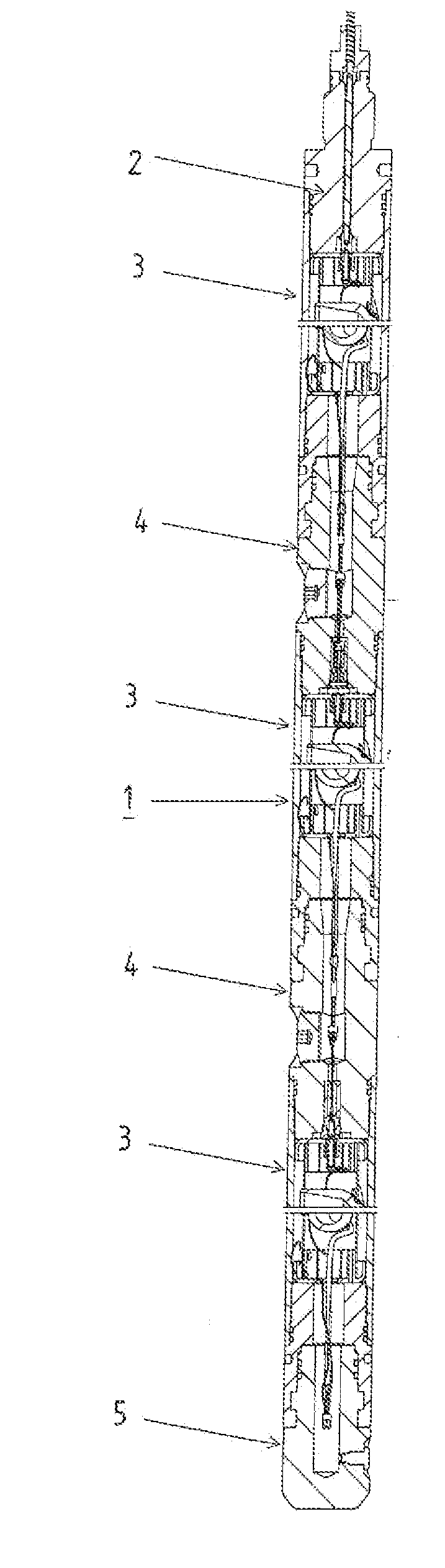
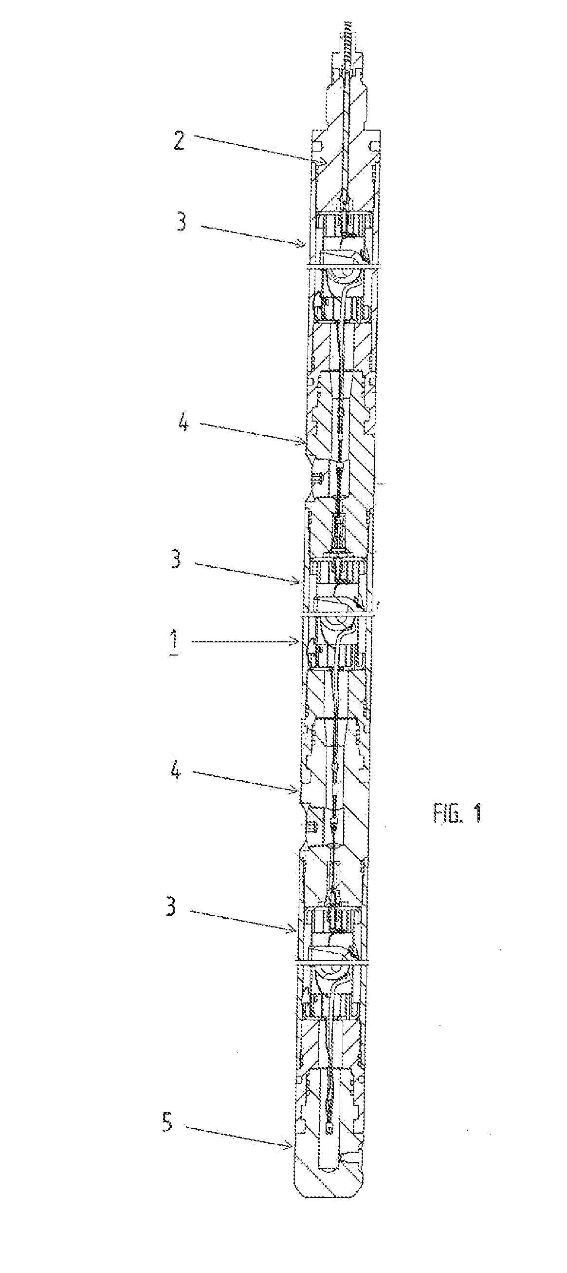
[0076]In relation to FIG. 1, the gun assembly (1) has a firing head (2), three guns (3), each containing a charge-carrier, two tandems (4), three adaptors (6), and a bottom sub (5). The mentioned parts are tubular pieces provided at the ends of the elements of the machined joint that will be described briefly as they are not included within the sphere of protection of this invention.

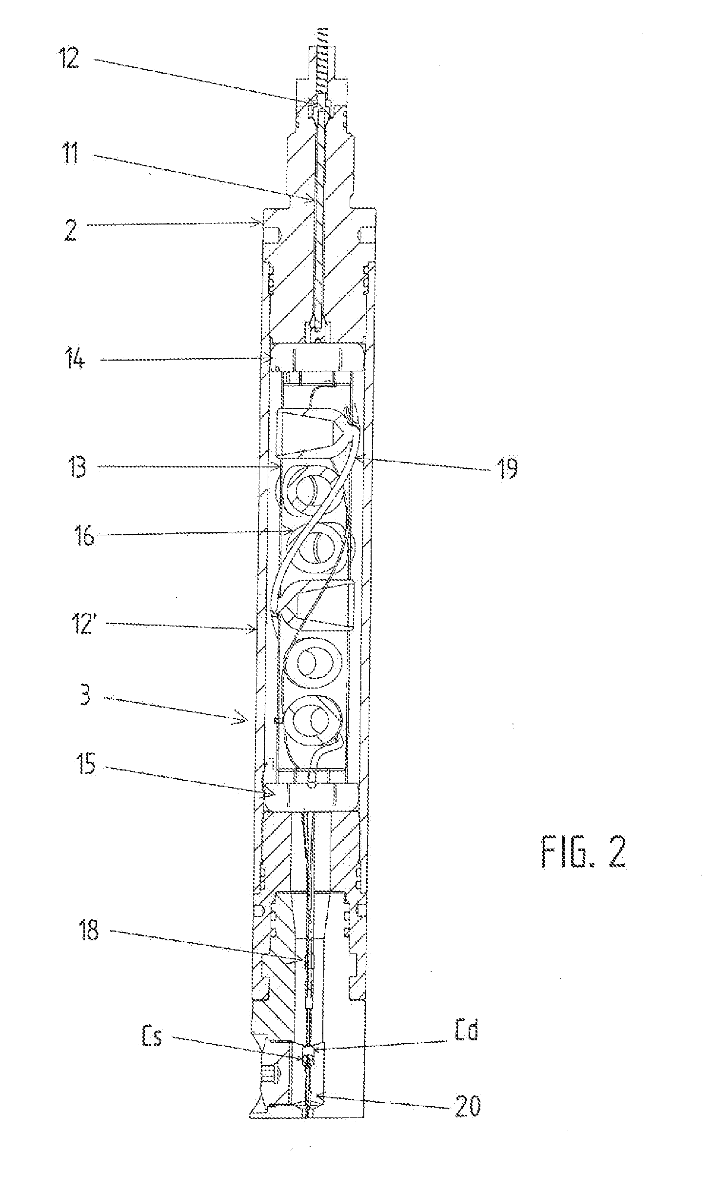
[0077]FIG. 2, shows the firing head (2) with an axial orifice through which an insulated metallic rod with a ‘spaghetti’ vein (11) passes. Through the upper conical contact (12) the rod connect...


PUM


Abstract

Electromechanical assembly for connecting a series of guns used in the perforation of petroleum producing wells. Each gun has a cylindrical housing for a charge-carrier loaded with explosive shaped-charges set in radial fashion. The charges are in contact with a detonating cord that is in contact with an electronically activated detonator. The series of guns are joined firmly by intermediary joints and terminate in a bottom sub on its lower extreme, where the series is initiated by a firing head which is connected to the surface with an electrical connection. It is possible to detonate the charge-carrier of each gun, beginning with the bottommost gun that remains active.

Description

FIELD OF THE INVENTION[0001]This invention refers in general to an integral assembly of guns to be used in the perforation of wells; particularly, it is directed to a new electromechanical assembly for connecting a series of guns used in the perforation of petroleum producing wells.[0002]The process of well perforation consists of the perforation of the metallic casing of the well, of the isolating cement surrounding the casing, and of the layers of rock in the producing formation by means of explosives housed within perforating-guns; achieving, through bore holes produced by shaped charges, a connection between the depths of the producing zone and the interior of the well.BACKGROUND OF THE INVENTION[0003]The perforation of petroleum producing wells is realized by lowering into the well various metallic perforating-guns of different lengths, the respective charge carriers of which are charged with shaped charges, connected by joints and fired in a vertical fashion, one after another...

Claims


Application Information

Patent Timeline
Patent Type & Authority Applications(United States)
IPC IPC(8): E21B43/116
CPCE21B43/1185
Inventor TASSAROLI, CARLOS JOSE
Owner TASSAROLI
Why Eureka
Try Eureka