Method and Apparatus for Managing Transmission of Power in a Power Transmission Network

a technology of transmission network and transmission network, applied in the integration of power network operation system, load forecasting in ac network, instruments, etc., can solve the problems of high cost of over-production of energy, low production, and energy production, and achieve the effect of reducing the amount of surplus power

Inactive Publication Date: 2013-02-21
GRIDMANAGER
View PDF9 Cites 58 Cited by
  • Summary
  • Abstract
  • Description
  • Claims
  • Application Information

AI Technical Summary

Benefits of technology

[0021]In general, transformers are often a vital part of the utility grid. Furthermore, a transformer is a cost expensive and time consuming part of the grid to exchange or repair in case of breakdown. By monitoring one or more parameters of the transformer during a period of time and performing a regulation of the power at the lower voltage side of the transformer based on one or more reference values, a protection of the transformer is achieved, thus significantly reducing the risk of disadvantageous loads on the transformer.
[0210]This is advantageous since certain power transmission lines (e.g. transmission or distribution lines) especially old power transmission lines in the utility grid were dimensioned to transport a smaller amount of power than recently installed power transmission lines. Hence due to expansion of the power consumption form the utility grid e.g. because of new power consumers and / or power producers are connected to existing power transmission lines of the utility grid it is advantageous to be able to route the transmission of power through the utility grid.

Problems solved by technology

On of the problems related to the consumer grid is that the production of energy at some point will have to match the consumption.
This may lead to expensive over production of energy due to the fact that it is generally unacceptable that the power production is too low at any time.
Moreover, this process involves that the grid will have to support this non-productive transport of energy.

Method used


Image

  • Method and Apparatus for Managing Transmission of Power in a Power Transmission Network
  • Method and Apparatus for Managing Transmission of Power in a Power Transmission Network
  • Method and Apparatus for Managing Transmission of Power in a Power Transmission Network

Examples


Embodiment Construction

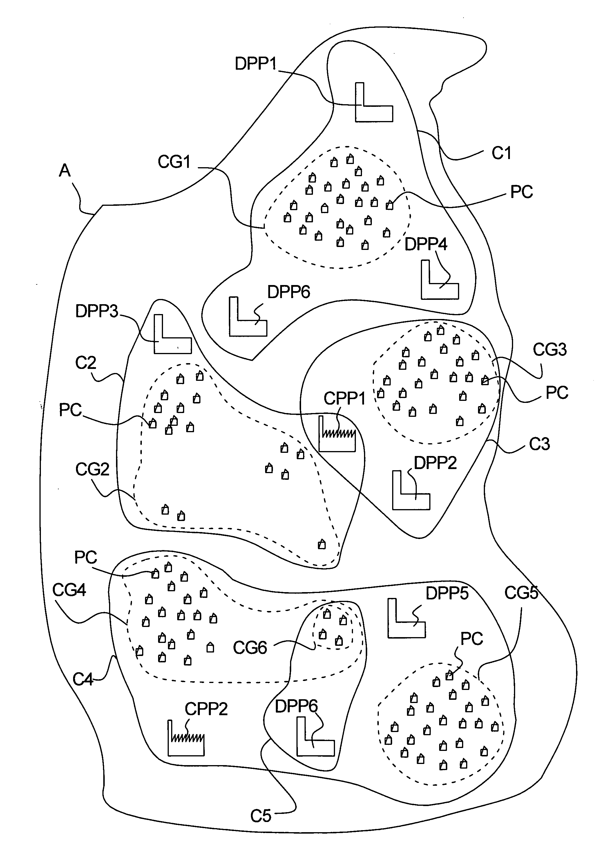
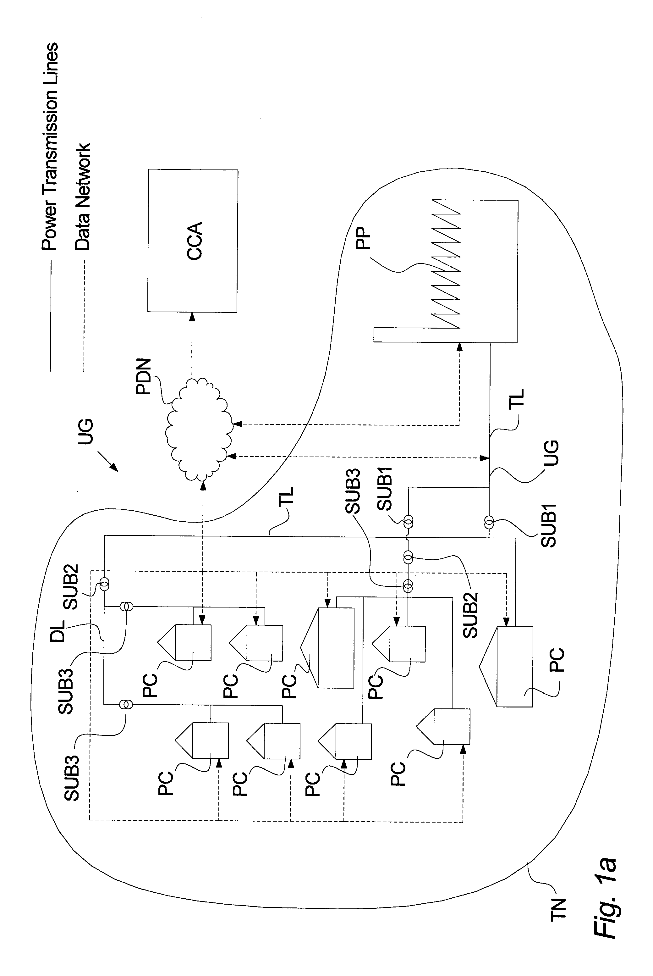
[0233]FIG. 1a illustrates a transmission network TN comprising a power producer PP, a utility grid UG and a plurality of power consumers PC consuming power produced by the power producer PP. The power producer PP may either be a central power plant CPP or a decentralized power plants DPP as described below. Furthermore, a central control arrangement CCA is (e.g. by means of a public data network such as the internet) connected to elements of the transmission network, e.g. power consumers PC power producers PP, substations SUB and the like via one or more data communication network DN. An example of data communication networks may be wired network(s) such as LAN (LAN; Local Area Network(s)), optical fibre network(s), coaxial network(s) or the like, and / or wireless network(s) such as WLAN (WLAN; Wireless Local Area Network), a mobile internet, a GSM network (GSM; Global System for Mobile communication) or any other suitable network and combinations thereof.

[0234]The utility grid UG co...


PUM


Abstract

The invention relates to a method of managing transmission of power in a power transmission network, said method comprising the steps of: establishing utility grid characteristic comprising at least one reference value based on at least one parameter reflecting the state of said transformer, continuously monitoring said at least one parameter reflecting the state of said transformer, and continuously controlling power consumption and / or power production at the lower voltage side of said transformer based on said monitoring of said at least one parameter reflecting the state of said transformer, said controlling of said power consumption and / or said power production comprising regulating said power consumption of one or more of said plurality of power consumers and / or regulating said power production of one or more decentralized power producers located at said lower voltage side of said transformer, so as to comply with said established reference value.

Description

BACKGROUND OF THE INVENTION[0001]The need of electrical power is growing, and there is an increased focus on producing more electrical power by means of renewable energy to spare the environment. This among other things increases the demand to the utility grid since more electric power producers are connected to the utility grid at different locations in the utility grid to comply with the growing need for power and demands for green energy / renewable energy.[0002]On of the problems related to the consumer grid is that the production of energy at some point will have to match the consumption. This may lead to expensive over production of energy due to the fact that it is generally unacceptable that the power production is too low at any time.[0003]This may even lead to that power producers will have to pay power producers, e.g. in other countries or states, in order to get rid of the over production. Moreover, this process involves that the grid will have to support this non-producti...

Claims


Application Information

Patent Timeline
Patent Type & Authority Applications(United States)
IPC IPC(8): H02J3/38G06Q10/04G06Q50/06
CPCG06Q10/04G06Q50/06H02J3/00H02J3/14H02J13/0006H02J2003/003Y04S10/54Y04S10/60Y04S10/30Y04S40/22Y02E60/74Y02E60/76H02J2003/007H02J2203/20H02J3/003H02J13/00002H02J13/00034Y02E60/00Y04S40/20Y04S20/222Y02B70/3225H02J2310/60H02J3/144Y04S10/50
Inventor BIRKELUND, MOGEN
Owner GRIDMANAGER
Why Eureka
Try Eureka