Method and apparatus for misstep detection and recovery in a stepper motor

a stepper motor and misstep detection technology, applied in the direction of electrical equipment, control systems, dynamo-electric converter control, etc., can solve the problems of reducing the probability of missteps (i.e., electrical cycles, slipping or losing poles) during operation, and entail significant drawbacks in actual positioning capability,

Active Publication Date: 2013-02-21
ORIENTAL MOTOR BOSTON TECH GROUP
View PDF9 Cites 17 Cited by
  • Summary
  • Abstract
  • Description
  • Claims
  • Application Information

AI Technical Summary

Benefits of technology

[0011]It is the broad object of the present invention to provide a novel stepper motor apparatus and system, and a novel method utilizing the same, wherein and whereby missteps, are readily detected using periodic position feedback data, to thereby enable immediate recovery of lost motor steps.
[0031]Thus, to enable misstep detection and motor step recovery in a stepper motor system, using an incorporated position-feedback device, position deviation is computed periodically and cyclically by subtracting the feedback position from the corresponding commanded position (i.e., the position to which the rotor should have arrived at any given instant, following the commanded trajectory) to determine the load angle and operating status of the motor. The load angle will normally lie within the established allowable limits, and stepper operation along the programmed trajectory will therefore simply be maintained. In instances in which the load angle value exceeds the specified zone (i.e., passes beyond the limits of the established range, in a positive or a negative direction), however, and thereby indicates that a misstep has occurred, the controller will take immediate action to recover all lost motor steps, and to reestablish synchronism and then continue to attain the target position, with minimal loss of time.

Problems solved by technology

Operating a stepper motor in a simple, open-loop mode entails a significant drawback, however, with regard to actual positioning capability.
Because that assumption is known to be generally incorrect, in order to accommodate it the motor torque utilization by the load is normally kept below 50% of theoretical or design capacity; since the greater the torque margin available, the lower will be the likelihood that missteps (i.e., slipped or lost poles, or electrical cycles) will occur during operation.
If, on the contrary, the external load applied were to exceed the maximum torque capability of the motor for any reason (such as, for example, due to momentary mechanical binding), one or more missteps may occur, and the motor may stall completely throughout the remainder of the commanded trajectory, resulting in a failure to reach the target position.
A major drawback of such systems resides in the fact that, depending upon the position at which the motor stalled during profiling, the subsequently applied correction move can take an inordinate amount of time (e.g., as long as it would have taken to complete the previous, intended motion).
While missteps can thereby be avoided, other difficulties are often associated with such methods.
Firstly, the position-feedback device must have a relatively high-resolution capability in order to accommodate a high pole count; that significantly increases the cost of the system, and high-resolution devices are, of necessity, usually larger and more difficult to manufacture than are otherwise comparable low-resolution devices.
And moreover, PID controller gains must be tuned properly to the load condition, and start-up positions can be inaccurate due to encoder absolute error or external loads that produce a bias between the stator command position and the rotor with encoder position, thereby compromising peak torque and control stability.

Method used


Image

  • Method and apparatus for misstep detection and recovery in a stepper motor
  • Method and apparatus for misstep detection and recovery in a stepper motor
  • Method and apparatus for misstep detection and recovery in a stepper motor

Examples


example one

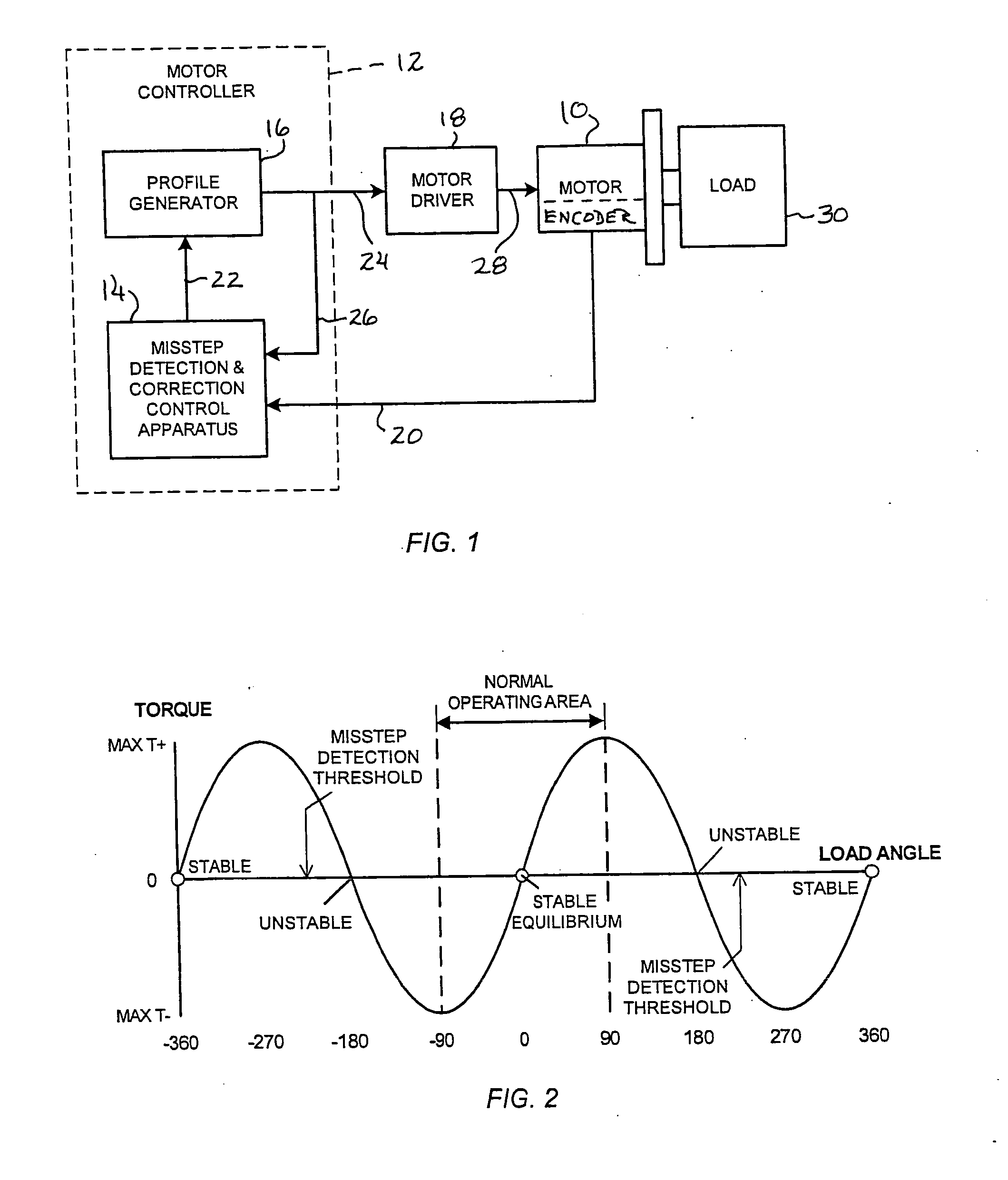
[0061]The stepper motor resolution is set for commutation at 10,000 steps per revolution, equivalent to 200 steps per electrical cycle and 50 steps (scaling factor) per encoder count. The misstep detection threshold is set at plus and minus 225° (defining the limits of the load angle value range for normal motor operation), and the offset or bias value (NX) is 75 steps (200 steps per electrical cycle times F / 360°, where F has the empirically assigned value 135°, as discussed above). The profile generator of the motor system is programmed to generate a trapezoidal motion in the positive direction with an Index distance of 200,000 steps, a running velocity of 1,000 rpm, and a starting speed of 50 rpm.

Part A (No Misstep)

[0062]The first commanded position (PC) is arbitrarily deemed to be 10 revolutions away from the starting position of the rotor (i.e., 100,000 steps). If the encoder counter (EC) contains a value of 2,000 counts [10 revolutions*200 counts / revolution], the system would h...

example two

[0069]The stepper motor resolution is set for commutation at 200 steps per revolution, equivalent to four steps per electrical cycle and a scaling factor of one step per encoder count. The misstep detection threshold is again set at plus and minus 225°, equivalent here to two motor steps (four steps per electrical cycle*225° / 360°, with the 0.5 step remainder being ignored); the bias value (NX) is one step (four steps per electrical cycle times 135° / 360°, with the 0.5 step remainder again being ignored). In this Example, a relatively slow processor is employed, with access to the encoder, for signal sampling, being had at one-millisecond intervals. The profile generator of the system is programmed to generate a trapezoidal motion in the positive direction, with an Index distance of 5,000 steps, a running velocity of 1,000 rpm, and a starting speed of 50 rpm.

[0070]The first commanded position (PC) is deemed to be 11 revolutions away from the starting position of the rotor (i.e., 2,200...


PUM


Abstract

A stepper motor system and apparatus use a position-feedback device, which may have a resolution capability as low as 200 counts per motor shaft revolution, for misstep detection and motor step recovery. In use of the system, position deviation is computed periodically and cyclically, by subtracting the feedback position from the corresponding commanded position, to determine the load angle, implicitly, and the operating status of the motor. If the load angle is within an established allowable range of values, normal stepper operation along the programmed trajectory is maintained, without adjustment. A load angle that exceeds the limits of that range however indicates that a misstep has occurred, and the system controller initiates immediate action to recover lost motor steps, to reestablish synchronism, and to then continue toward the final target position, with minimal loss of time.

Description

CROSS-REFERENCE TO RELATED APPLICATION[0001]This application claims the benefit of U.S. Provisional Patent Application No. 61 / 575,362, entitled “Method and Apparatus for Misstep Recovery In Stepper Motor That Require Very Low Resolution Position Feedback,” filed Aug. 19, 2011, the entire specification of which is incorporated hereinto by reference.BACKGROUND OF THE INVENTION[0002]Stepper motors and servo motors are typical of devices that are used where precise position capability is required in mechanical positioning systems. Such motors are employed widely in numerous applications, including for example factory and office automations, food processing installations, packaging applications, inspection machines, medical devices and apparatus, etc.[0003]Unlike servo motors, which inherently require the incorporation of feedback devices (such as encoders and resolvers) having at least fairly high resolution capability, and closed-loop control (e.g., a PID), to afford constant detection...

Claims


Application Information

Patent Timeline
Patent Type & Authority Applications(United States)
IPC IPC(8): H02P8/38
CPCH02P8/38
Inventor VU, HUNG D.
Owner ORIENTAL MOTOR BOSTON TECH GROUP
Why Eureka
Try Eureka