Display panel

Active Publication Date: 2013-02-21
AU OPTRONICS CORP
View PDF4 Cites 10 Cited by
  • Summary
  • Abstract
  • Description
  • Claims
  • Application Information

AI Technical Summary

Benefits of technology

[0005]It is therefore one of the objectives of the present invention to pro

Problems solved by technology

This extra photolithography process would increase fabrication cost, wh

Method used


Image

  • Display panel
  • Display panel
  • Display panel

Examples


Embodiment Construction

[0013]To provide a better understanding of the present invention to the skilled users in the technology of the present invention, preferred embodiments will be detailed as follows. The preferred embodiments of the present invention are illustrated in the accompanying drawings with numbered elements to elaborate the contents and effects to be achieved.

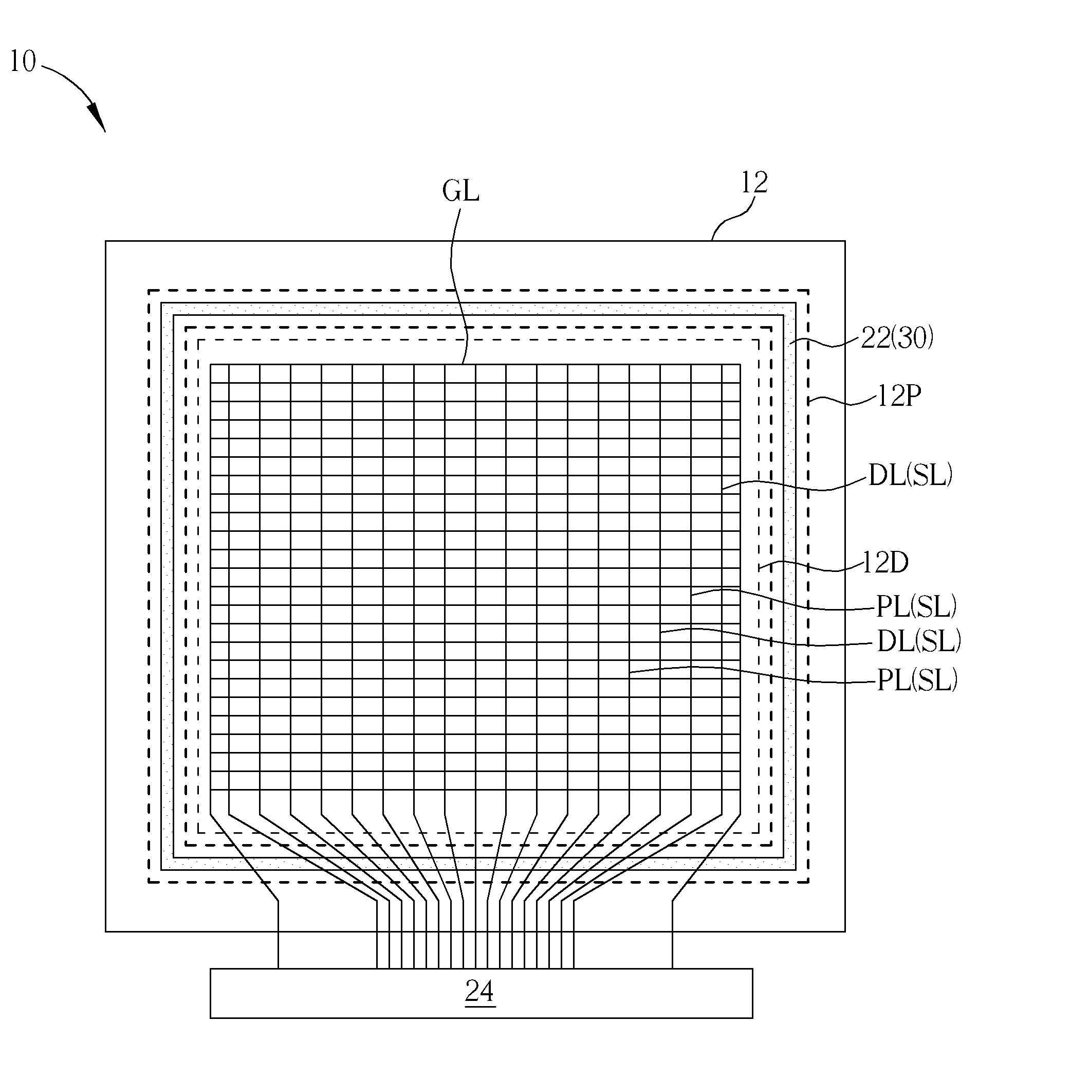
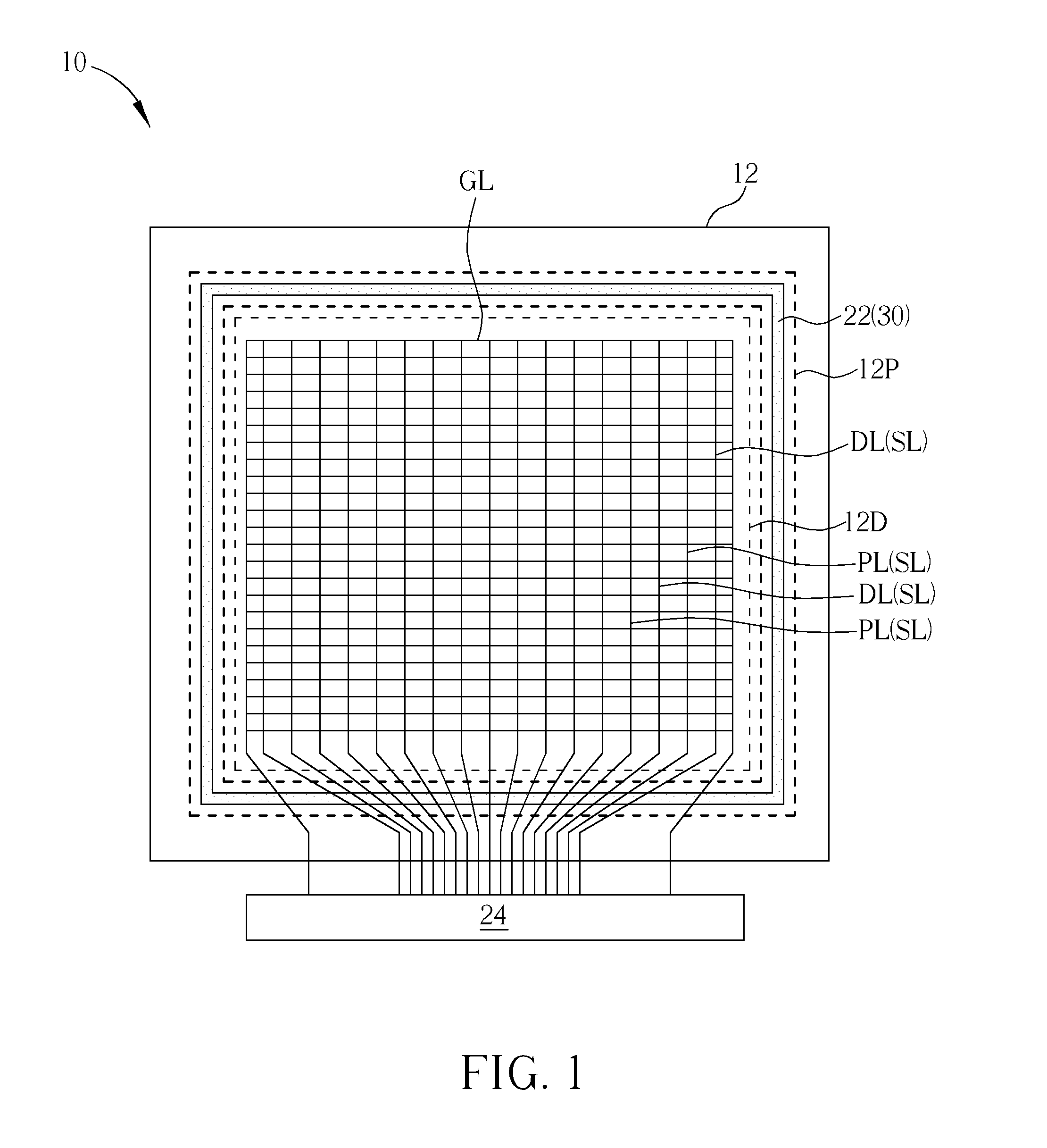
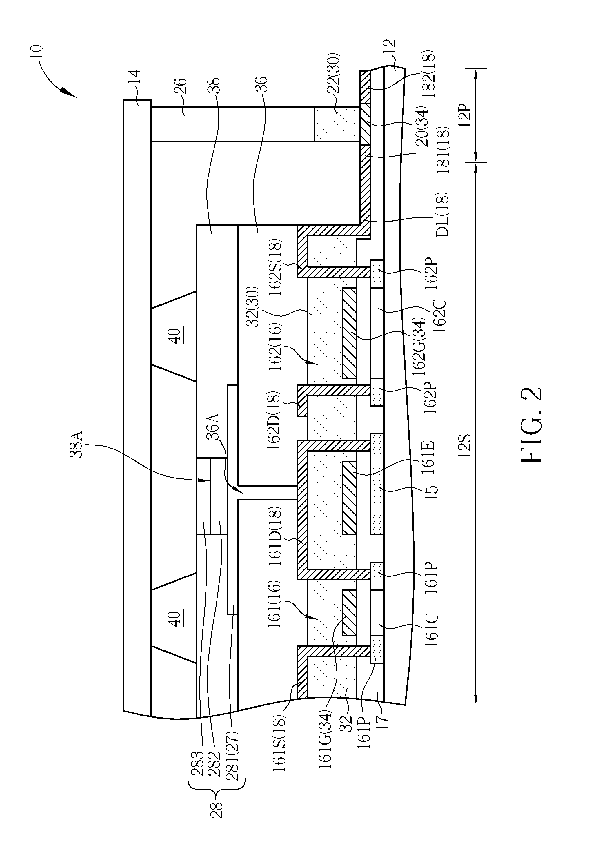
[0014]Please refer to FIG. 1 and FIG. 2. FIG. 1 illustrates a top view of a display panel according to a first preferred embodiment of the present invention, and FIG. 2 illustrates a cross-sectional view of a display panel according to a first preferred embodiment of the present invention. To highlight the features of the display panel of the present embodiment, some parts of the display panel are not drawn in FIG. 1 or FIG. 2. As shown in FIG. 1 and FIG. 2, the display panel 10 of this embodiment includes a substrate 12, an encapsulation substrate 14, a plurality of signal lines SL, a plurality of thin film transistor (TFT) devices 16,...


PUM


Abstract

A display panel includes a substrate, a TFT device, a patterned dielectric layer, a patterned metal layer and a bridge line. The TFT device is disposed in a display region. The patterned dielectric layer includes an ILD layer disposed over the TFT device, and a sealant stage disposed in a peripheral region. The patterned metal layer includes a signal line disposed on the ILD layer, and a first connecting line and a second connecting line. The first connecting line is disposed in an inner side of the sealant stage facing the display region, and the first connecting line is electrically connected to the signal line. The second connecting line is disposed in an outer side of the sealant stage opposite to the display region. The bridge line is disposed under the sealant stage, and the first connecting line and the second connecting line are electrically connected through the bridge line.

Description

BACKGROUND OF THE INVENTION[0001]1. Field of the Invention[0002]The present invention relates to a display panel, and more particularly, to a display panel including an inter-layered dielectric (ILD) layer and a sealant stage made of the same patterned dielectric layer.[0003]2. Description of the Prior Art[0004]A display panel generally includes an array substrate, an encapsulation substrate, a light-emitting array formed on the array substrate, and a sealant formed between the array substrate and the encapsulation substrate to bond the array substrate and the encapsulation substrate. In a conventional display panel, the sealant is required to be cured by laser irradiation for providing adhesion between the array substrate and the encapsulation substrate. Heat, however, will generate during laser irradiation. To prevent the devices formed in the array substrate under the sealant from being damaged by heat, a material layer e.g. an inorganic material layer served as a sealant stage t...

Claims


Application Information

Patent Timeline
IPC IPC(8): G09G3/30
CPCH01L51/524H01L27/3276H01L27/3258H10K59/124H10K59/131H10K50/841
Inventor HUANG, YEN-SHIHYEH, CHIA-YUANLEE, BO-FENGCHIU, TA-WEI
Owner AU OPTRONICS CORP
Why Eureka
Try Eureka