Electric Vehicle Load Management

a technology for electric vehicles and load management, applied in process control, process and machine control, battery/fuel cell control arrangement, etc., can solve problems such as strain on existing electric power transmission and distribution systems, and achieve the effect of reducing the amount of charg

Inactive Publication Date: 2013-02-21
SIEMENS CORP
View PDF35 Cites 38 Cited by
  • Summary
  • Abstract
  • Description
  • Claims
  • Application Information

AI Technical Summary

Benefits of technology

[0010]Another aspect of the invention provides at each neighborhood charging controllers: downloading the day ahead energy price from the utility control center, if any competition interval is capped, reducing

Problems solved by technology

However, the popularity of EVs will result in a strain on the

Method used


Image

  • Electric Vehicle Load Management
  • Electric Vehicle Load Management
  • Electric Vehicle Load Management

Examples


Embodiment Construction

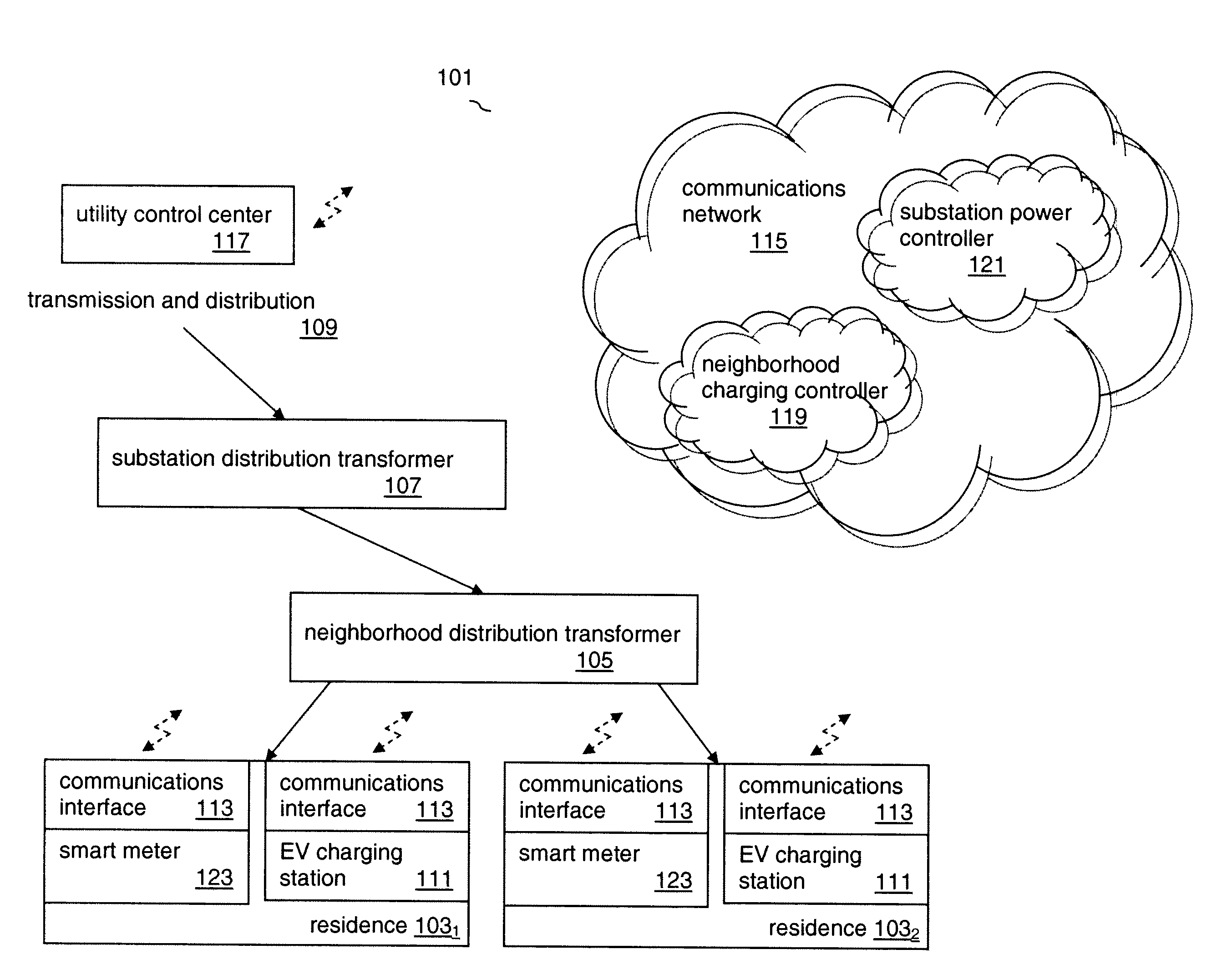
[0016]Embodiments of the invention will be described with reference to the accompanying drawing figures wherein like numbers represent like elements throughout. Before embodiments of the invention are explained in detail, it is to be understood that the invention is not limited in its application to the details of the examples set forth in the following description or illustrated in the figures. The invention is capable of other embodiments and of being practiced or carried out in a variety of applications and in various ways. Also, it is to be understood that the phraseology and terminology used herein is for the purpose of description and should not be regarded as limiting. The use of “including,”“comprising,” or “having,” and variations thereof herein is meant to encompass the items listed thereafter and equivalents thereof as well as additional items.

[0017]The terms “connected” and “coupled” are used broadly and encompass both direct and indirect connecting, and coupling. Furthe...


PUM


Abstract

A distributed and collaborative load balancing method is disclosed that uses a utility's existing transmission and distribution system to charge an Electric Vehicle (EV) using load shifting over time and minimizes the overall cost of energy usage to charge EVs. The collaborative load balancing ensures grid reliability.

Description

CROSS REFERENCE TO RELATED APPLICATIONS[0001]This application claims the benefit of U.S. Provisional Application No. 61 / 523,500, filed on Aug. 15, 2011, the disclosure which is incorporated herein by reference in its entirety.BACKGROUND OF THE INVENTION[0002]The invention relates generally to electric utility load balancing. More specifically, the invention relates to a method for balancing the electrical load presented when charging Electric Vehicles (EVs).[0003]EVs are becoming increasingly popular. However, the popularity of EVs will result in a strain on the existing electric power transmission and distribution system.[0004]Typical EVs may require 10 to 18 kWh of charge per 100 km. Charging requirements vary by EV, battery technology, battery capacity and charge status. Charging stations, including charging stations installed at residential premises, must be capable of efficiently providing the required amount of current. The maximum amount of power that can be delivered to an e...

Claims


Application Information

Patent Timeline
IPC IPC(8): G06F1/26
CPCH02J3/32Y04S10/54B60L11/1842B60L11/1844B60L11/1848B60L11/1861G06Q10/06315B60L2260/54Y02T10/7044Y02T10/7005Y02T10/705Y02T90/163Y02T90/169Y02T90/14Y02T90/128Y04S10/126Y04S30/14Y02E60/721Y02T90/121Y02T10/7055H02J7/0027Y02T10/7072B60L55/00B60L53/63B60L53/665B60L58/12H02J2310/48H02J3/322Y02E60/00Y02T10/70Y02T90/12Y02T90/167Y02T90/16
Inventor AL FARUQUE, MOHAMMAD ABDULLAHJAFARI, MOHSEN A.LUDWIG, HARTMUTDALLORO, LIVIOHAQUE, MD EHTESAMUL
Owner SIEMENS CORP
Why Eureka
Try Eureka